
Commander 4WD V8-4.7L VIN N (2006)
Leak Detection Pump: Description and Operation
Natural Vac Leak Detection
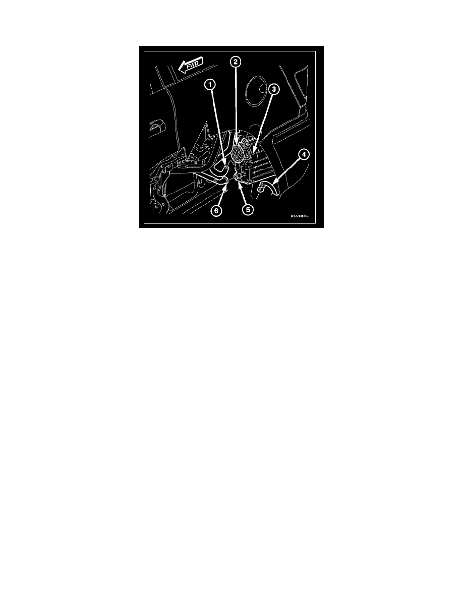
The NVLD (Natural Vacuum Leak Detection) pump (2) is attached to the EVAP canister (3). This assembly is located in the left-rear quarter-panel
behind the left-rear tire. Refer to NVLD.
The Natural Vacuum Leak Detection (NVLD) system is the next generation evaporative leak detection system that will first be used on vehicles
equipped with the Next Generation Controller (NGC). This new system replaces the leak detection pump as the method of evaporative system leak
detection. This is to detect a leak equivalent to a 0.0209 (0.5 mm) hole. This system has the capability to detect holes of this size very dependably.
The basic leak detection theory employed with NVLD is the "Gas Law". This is to say that the pressure in a sealed vessel will change if the temperature
of the gas in the vessel changes. The vessel will only see this effect if it is indeed sealed. Even small leaks will allow the pressure in the vessel to come to
equilibrium with the ambient pressure. In addition to the detection of very small leaks, this system has the capability of detecting medium as well as large
evaporative system leaks.
A vent valve seals the canister vent during engine off conditions. If the vapor system has a leak of less than the failure threshold, the evaporative system
will be pulled into a vacuum, either due to the cool down from operating temperature or diurnal ambient temperature cycling. The diurnal effect is
considered one of the primary contributors to the leak determination by this diagnostic. When the vacuum in the system exceeds about 19 H2O (0.25
KPA), a vacuum switch closes. The switch closure sends a signal to the NGC. The NGC, via appropriate logic strategies, utilizes the switch signal, or
lack thereof, to make a determination of whether a leak is present.
The NVLD device is designed with a normally open vacuum switch, a normally closed solenoid, and a seal, which is actuated by both the solenoid and a
diaphragm. The NVLD is located on the atmospheric vent side of the canister. The NVLD assembly may be mounted on top of the canister outlet, or
in-line between the canister and atmospheric vent filter. The normally open vacuum switch will close with about 19 H2O (0.25 KPA) vacuum in the
evaporative system. The diaphragm actuates the switch. This is above the opening point of the fuel inlet check valve in the fill tube so cap off leaks can
be detected. Submerged fill systems must have recirculation lines that do not have the in-line normally closed check valve that protects the system from
failed nozzle liquid ingestion, in order to detect cap off conditions.
The normally closed valve in the NVLD is intended to maintain the seal on the evaporative system during the engine off condition. If vacuum in the
evaporative system exceeds 39 to 69 H2O (0.75 to 1.5 KPA), the valve will be pulled off the seat, opening the seal. This will protect the system from
excessive vacuum as well as allowing sufficient purge flow in the event that the solenoid was to become inoperative.
The solenoid actuates the valve to unseal the canister vent while the engine is running. It also will be used to close the vent during the medium and large
leak tests and during the purge flow check. This solenoid requires an initial 1.5 amps of current to pull the valve open, but after 100 milli-seconds, will
be duty cycled down to an average of about 150 mA for the remainder of the drive cycle.
Another feature in the device is a diaphragm that will open the seal in the NVLD with pressure in the evaporative system. The device will "blow off" at
about 0.59 H2O (0.12 KPA) pressure to permit the venting of vapors during refueling. An added benefit to this is that it will also allow the tank to
"breathe" during increasing temperatures, thus limiting the pressure in the tank to this low level. This is beneficial because the induced vacuum during a
subsequent declining temperature will achieve the switch closed (pass threshold) sooner than if the tank had to decay from a built up pressure.
The device itself has 3 wires: Switch sense, solenoid driver and ground. It also includes a resistor to protect the switch from a short to battery or a short
to ground. The NGC utilizes a high-side driver to energize and duty-cycle the solenoid.