
Grand Cherokee 2WD L6-242 4.0L VIN S MFI (1993)
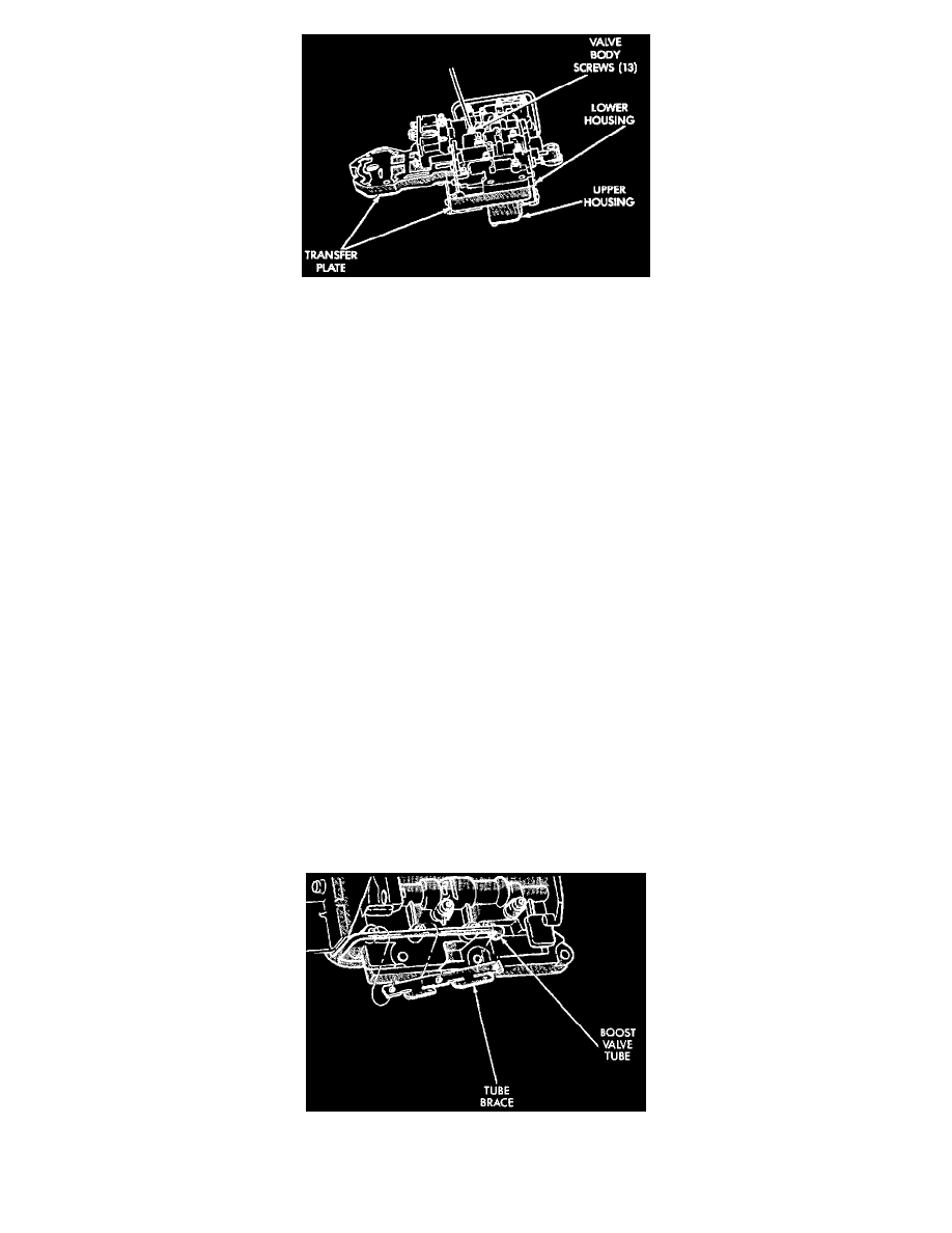
Fig. 132 Installing Lower Housing On Transfer Plate And Upper Housing
(4) Install lower housing on assembled transfer plate and upper housing (Fig. 132).
(5) Install and start valve body screws by hand. Then tighten screws evenly to 4 N.m (35 in. lbs.) torque. Start at center and work out to sides when
tightening screws (Fig. 132).
Upper Housing Valve And Plug Installation (Figs. 122,123,124
(1) Lubricate valves, plugs, springs with clean transmission fluid.
(2) Assemble regulator valve line pressure plug, sleeve, throttle plug and spring. Insert assembly in upper housing and install cover plate. Tighten
cover plate screws to 4 N.m (35 in. lbs.) torque.
(3) Install 1-2 and 2-3 shift valves and springs.
(4) Install 1-2 shift control valve and spring.
(5) Install shift valve cover plate.
(6) Install shuttle valve as follows:
(a) Insert plastic guides in shuttle valve secondary spring and install spring on end of valve.
(b) Hold shuttle valve in place.
(c) Compress secondary spring and install E-clip in groove at end of shuttle valve.
(d) Verify that spring and E-clip are properly seated before proceeding.
(7) Install shuttle valve cover plate. Tighten cover plate screws to 4 N.m (35 in. lbs.) torque.
(8) Install 1-2 and 2-3 valve governor plugs in valve body.
(9) Install shuttle valve primary spring and throttle plug.
(10) Align and install governor plug cover. Tighten cover screws to 4 N.m (35 in. lbs.) torque.
(11) Install manual valve.
(12) Install throttle valve and spring.
(13) Install kickdown valve and detent.
(14) Install pressure regulator valve.
(15) Install switch valve.
Boast Valve Tube And Brace Installation
(1) Position valve body assembly so lower housing is facing upward (Fig. 113).
(2) Lubricate tube ends and housing ports with transmission fluid or petroleum jelly.
(3) Start tube in lower housing port first. Then swing tube downward and work opposite end of tube into upper housing port (Fig. 113).
(4) Insert and seat each end of tube in housings.
Fig. 133 Boost Valve Tube And Brace Installation
(5) Slide tube brace under tube and into alignment with valve body screw holes (Fig. 133).
(6) Install and finger tighten three screws that secure tube brace to valve body housings (Fig. 133).