
Wagoneer L6-242 4.0L VIN M FI (1988)
k.
Insert shift tube in lower end of steering column jacket, then rotate shift tube until upper key slides into gear selector housing keyway.
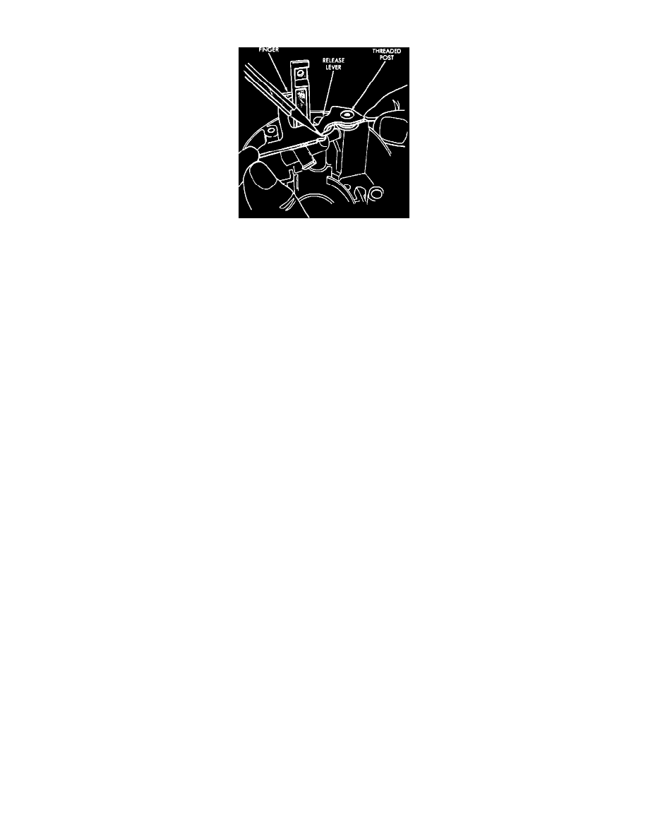
Fig. 37 Key release lever installation
2.
On models with console shift, proceed as follows:
a.
Install lock sector on lock sector shaft in the ignition lock cylinder housing.
b.
Install rack preload spring. Ensure bowed side of spring contacts the lock rack when rack is installed.
c.
Assemble lock bolt and rack, then install rack assembly in ignition lock cylinder housing. Ensure block tooth in rack engages block tooth
of lock sector.
d.
Install key release lever return spring over threaded post on ignition lock cylinder housing.
e.
Install key release lever finger into the lock rack slot, then position the hole in the lever over the threaded post on ignition lock cylinder
housing. Ensure inner end of spring contacts the release lever.
f.
Raise key release lever slightly and install the end of the lever spring between the lever and boss on the housing.
g.
Position shroud on ignition lock cylinder housing and install attaching screws. Torque screws to 18 inch lbs.
h.
Install short hooked end of remote rod in the lock rack.
i.
Install assembled housing and shroud on steering column jacket.
j.
Install attaching screws. Torque screws to 60 inch lbs.
3.
On all models, install ignition lock cylinder into housing, then the cylinder retaining screw. Torque screw to 40 inch lbs.
4.
Place ignition lock cylinder in the On position, then install key buzzer switch and contacts.
5.
Install ignition switch as follows:
a.
Insert ignition key, then place lock cylinder in Off-Unlock position.
b.
Position switch slider to Accessory, then back off two clicks to Off-Unlock position.
c.
Insert remote rod into switch slider hole, then install switch onto column jacket.
6.
Install lower bearing, adapter, retainer and spring clip on lower end of steering column.
7.
Install steering shaft in lower end of column and insert into upper end.
8.
Install turn signal switch into housing.
9.
Install turn signal switch attaching screws torquing to 35 inch lbs.
10.
Install dimmer switch actuator arm torquing attaching screw to 35 inch lbs.
11.
On models with cruise control, install switch harness in housing, then turn signal lever into column.
12.
On all models, install thrust washer, upper bearing preload spring and canceling cam on steering shaft.
13.
Align lock plate splines with steering shaft splines, then install lock plate.
14.
Install a new snap ring onto sleeve of compressor tool and install tool onto steering shaft.
15.
Compress lock plate and install snap ring into steering shaft groove.
16.
Install steering wheel, torque retaining nut to 25 ft. lbs.
17.
Connect battery ground cable.