
Discovery II
EMISSION CONTROL - V8
17-2-4
DESCRIPTION AND OPERATION
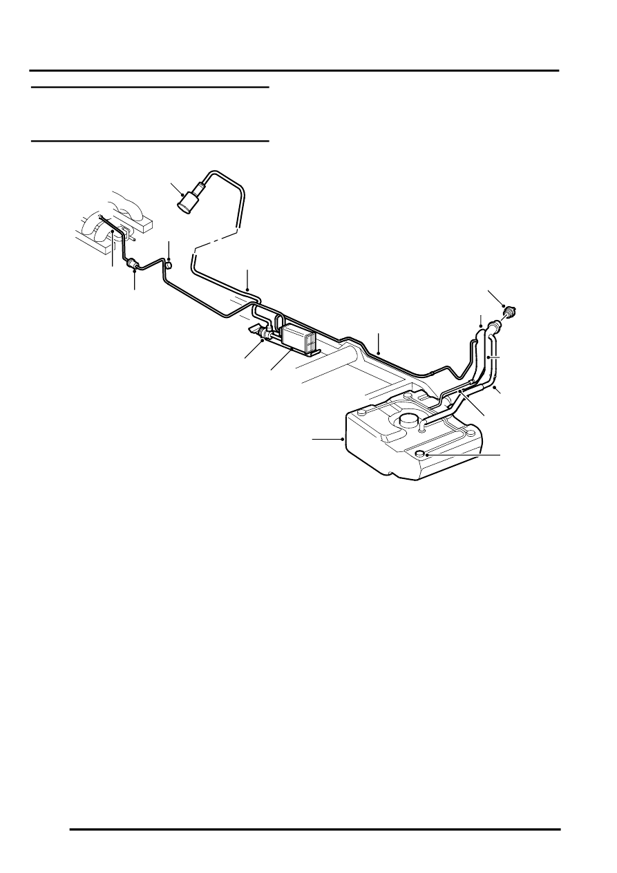
Evaporative emission system (with
positive pressure leak detection)
component layout (NAS only)
1 Purge valve
2 Service port
3 Air filter canister
4 EVAP canister breather tube
5 Leak detection pump
6 EVAP canister
7 Vent pipe – fuel tank to EVAP canister
8 Liquid vapour separator (metal)
9 Fuel filler cap
10 Fuel filler
11 Fuel tank breather assembly
12 Vent hose
13 Roll over valves (inside fuel tank)
14 Fuel tank
15 Purge line connection to engine manifold
M17 0208
3
1
7
4
14
11
6
8
10
13
12
15
2
5
9