
Discovery II
EMISSION CONTROL - V8
17-2-12 DESCRIPTION AND OPERATION
Fuel metering
For a satisfactory combustion process, precise fuel injection quantity, timing and dispersion must be ensured. If the
air:fuel mixture in the combustion chamber is not thoroughly atomized and dispersed during the combustion stroke,
some of the fuel may remain unburnt which will lead to high HC emissions.
Ignition timing
The ignition timing can be changed to minimise exhaust emissions and fuel consumption in response to changes due
to the excess air factor. As the excess air factor increases, the optimum ignition angle is advanced to compensate for
delays in flame propagation.
Exhaust Emission Control Components
The exhaust emission control components are described below:
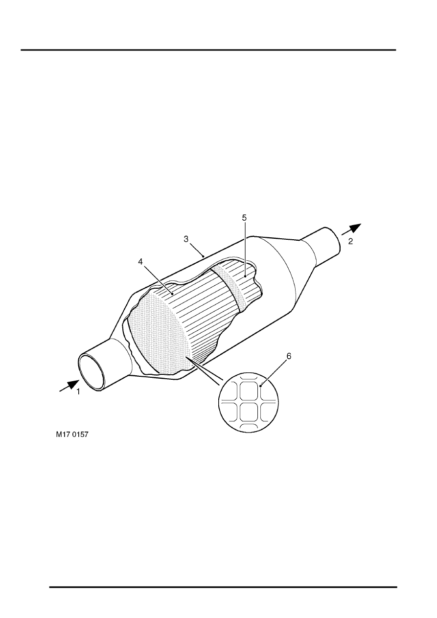
Catalytic converter
1 Exhaust gas from manifold
2 Cleaned exhaust gas to tail pipe
3 Catalytic converter outer case
4 1st ceramic brick
5 2nd ceramic brick
6 Honeycomb structure
The catalytic converters are located in each of the front pipes from the exhaust manifolds.
The catalytic converter's housings are fabricated from stainless steel and are fully welded at all joints. Each catalytic
converter contains two elements comprising of an extruded ceramic substrate which is formed into a honeycomb of
small cells with a density of 62 cells / cm
2
. The ceramic element is coated with a special surface treatment called
'washcoat' which increases the surface area of the catalyst element by approximately 7000 times. A coating is applied
to the washcoat which contains the precious elements Platinum, Palladium and Rhodium in the following relative
concentrations: 1 Pt : 21.6 PD : 1 Rh