
Discovery II
HEATING AND VENTILATION
80-10
DESCRIPTION AND OPERATION
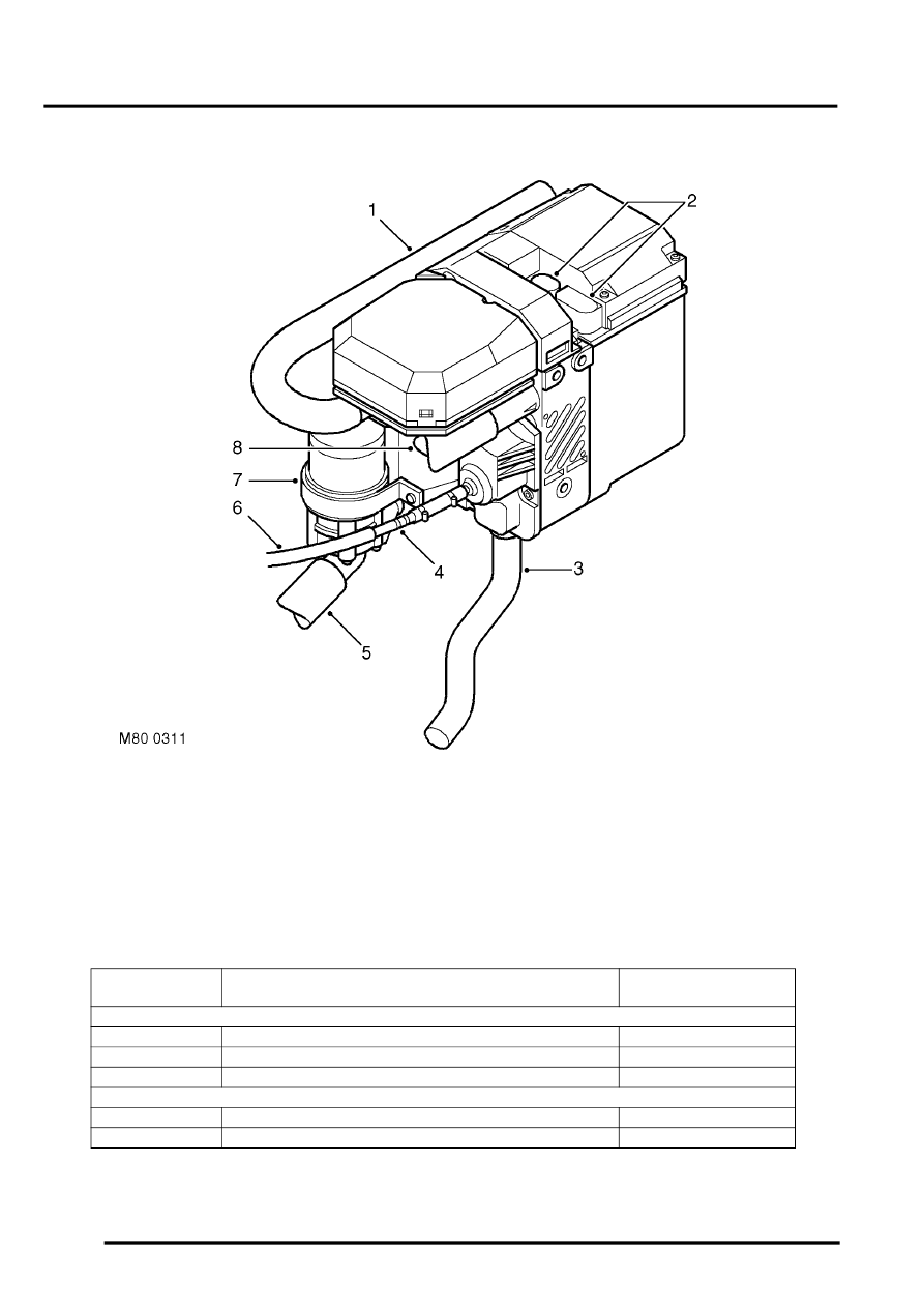
FBH unit
1 Air inlet hose
2 Electrical connectors
3 Exhaust pipe
4 Quick disconnect coupling
5 Coolant inlet hose
6 Fuel supply line
7 Circulation pump
8 Coolant outlet hose
The FBH unit is installed on the bulkhead in the engine compartment, on the side opposite the brake servo, and is
connected in series in the coolant supply to the heater assembly. Two electrical connectors on the top of the FBH unit
connect to the vehicle wiring.
FBH unit connector pin details
Connector/Pin
No.
Description
Input/Output
C0925
2
K line (diagnostics)
Input/Output
3
Alternator power supply
Input
6
FBH fuel pump
Output
C0926
1
Battery power supply
Input
2
Earth
-