
Freelander System Description and Operation
ENGINE MANAGEMENT SYSTEM - SIEMENS
18-4-30 DESCRIPTION AND OPERATION
Fuel Injectors
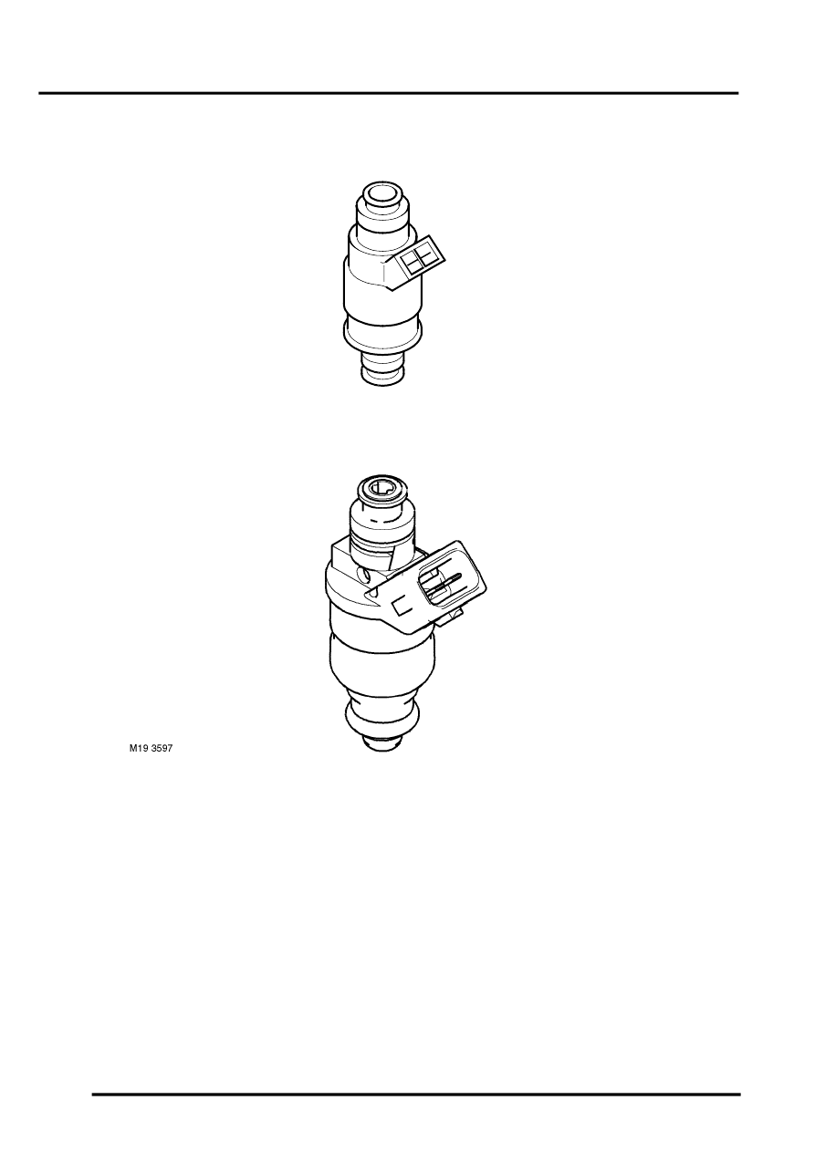
Fuel Injector – Up to 2003 Model Year
Fuel Injector – From 2003 Model Year
Up to 2003 Model Year
A split stream, air assisted fuel injector is installed for each cylinder. The injectors are located in the inlet manifolds
and connected to a common fuel rail assembly.
Each injector contains a pintle type needle valve and a solenoid winding. The needle valve is held closed by a return
spring. An integral nozzle shroud contains a ported disc, adjacent to the nozzles. 'O' rings seal the injector in the fuel
rail and the inlet manifold.
The solenoid winding of each injector receives a 12 volt supply from the ECM relay in the engine compartment
fusebox. To inject fuel, the ECM supplies an earth path to the solenoid winding, which energises and opens the needle
valve. When the needle valve opens, the two nozzles direct a spray of atomised fuel onto the back of each inlet valve.
Air drawn through the shroud and ported disc improves atomisation and directional control of the fuel. The air is
supplied from a dedicated port in the intake duct via a plastic tube and tracts formed in the gasket face of the intake
manifolds.
M19 2845A