
LR3/Disco 3
Climate Control System
Principles of Operation
For a detailed description of climate control operation, refer to the relevant Description and Operation section of the
workshop manual.
Inspection and Verification
1 . Verify the customer concern.
2 . Visually inspect for obvious signs of mechanical or electrical damage.
3 . If an obvious cause for an observed or reported concern is found, correct the cause (if possible) before proceeding to
the next step
4 . If the cause is not visually evident, verify the symptom and refer to the Symptom Chart.
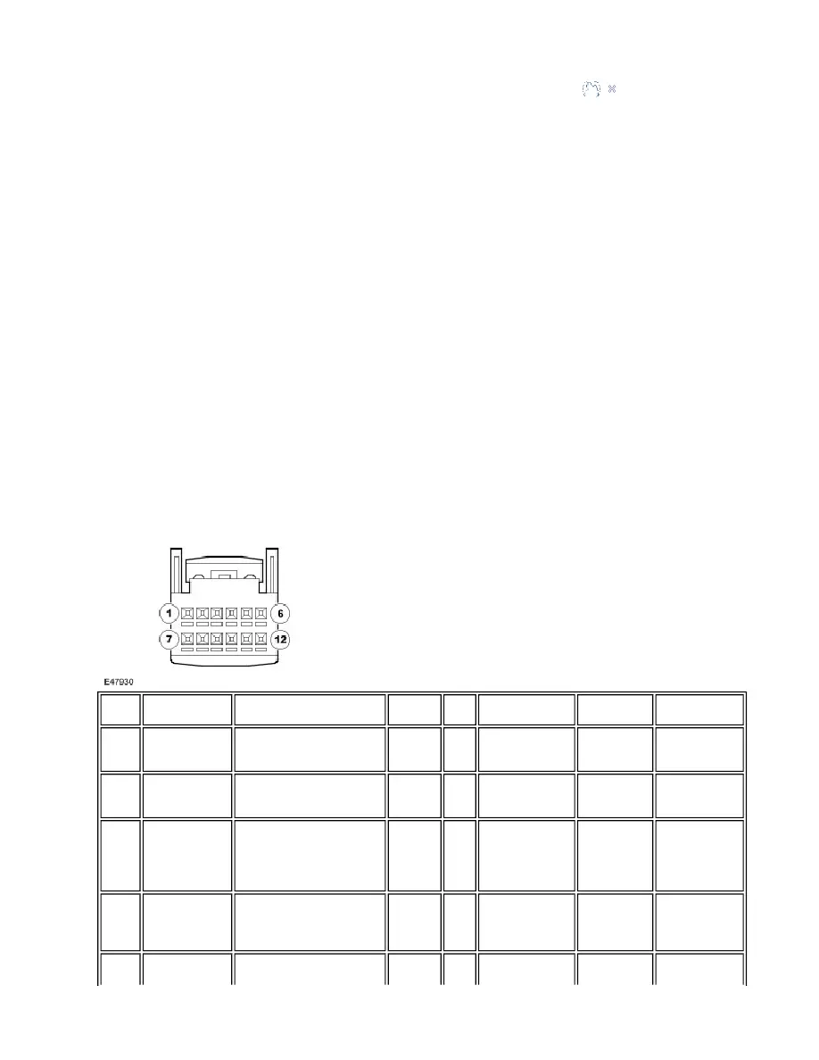
Connector Circuit Reference
Auxiliary Climate Control Module (ACCM) - C0695
NOTE :
Published : Mar 1, 2005
Discovery 3 vehicles with rear climate control only
Cavity
Description
Typical Condition - No
fault
DTC
PID
Symptom
Input/Output
Possible
Cause
1
Power supply
from ATC
module
Battery voltage when
ignition on. 0V when ATC
module in sleep mode
B1B7015 99A2
Rear A/C control
panel inoperative
Input
Open circuit,
short circuit to
ground
1
Power supply
from ATC
module
Battery voltage when
ignition on. 0V when ATC
module in sleep mode
B1B7311 99A2
Rear A/C control
panel inoperative
Input
Short circuit to
ground
2
LIN bus
9600 bps signal when ATC
module panel on. Average
signal approximately 9V,
depending on battery
voltage
B1B7088 None
Rear A/C control
panel inoperative
Input/Output Open circuit
3
Ground
Information not available
B1B7088 None
Rear A/C control
panel
inoperative. Fuse
may blow.
Input
Open circuit,
short circuit to
battery voltage
4
Rear blower
module power
Between 1.5V and 2.8V
depending on blower motor
None
999C
Information not
Output
Information not