
Range Rover P38
AIR CONDITIONING
19
DESCRIPTION AND OPERATION
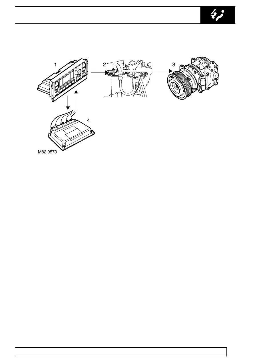
Compressor control diagram
1. ATC ECU
2. Dual pressure switch
3. Compressor
4. ECM
Compressor control
To engage the compressor clutch, the ATC ECU first
outputs an A/C request signal to the Engine Control
Module (ECM). If the ECM agrees that the
compressor can be engaged, it responds with an A/C
grant signal to the ATC ECU. The ATC ECU then
energises the compressor clutch via the dual pressure
switch. Automatic compressor operation is then
governed by the input from the evaporator
temperature sensor. If the temperature of the air
leaving the evaporator decreases to the point where
ice may form and restrict the air flow, the ATC ECU
de-energises the compressor clutch until the
temperature of the air leaving the evaporator
increases again.
The ATC ECU also de-energises the compressor
clutch if the A/C OFF switch is pressed, or if the ECM
withdraws the A/C grant signal (e.g. because of
engine overheat or high load conditions).