
Range Rover P38
AIR CONDITIONING
21
DESCRIPTION AND OPERATION
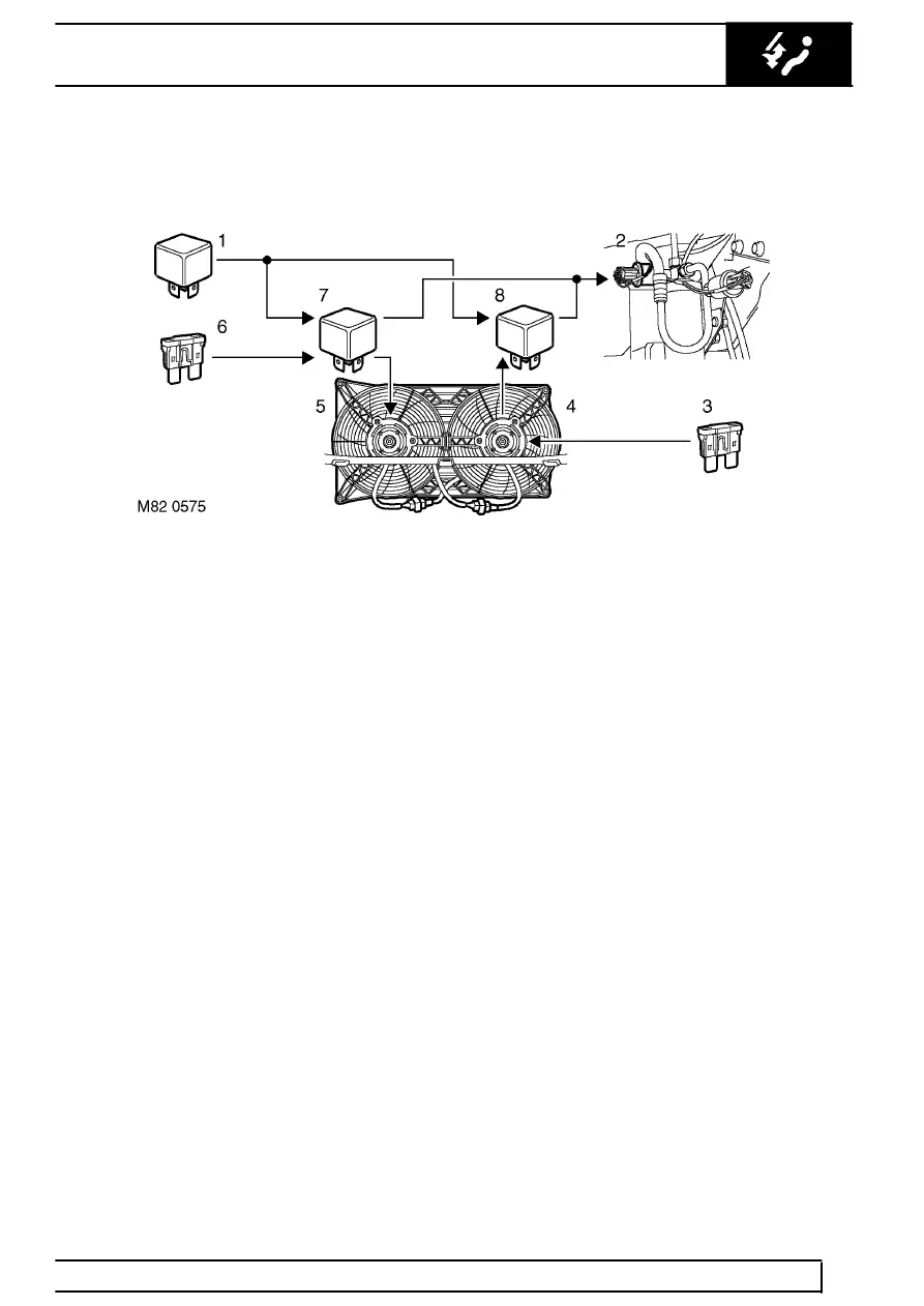
Condenser fans control diagram - fast speed
1. Relay 15 (ignition)
2. Dual pressure switch
3. Fuse 31 (battery power)
4. LH condenser fan
5. RH condenser fan
6. Fuse 36 (battery power)
7. Relay 14 (RH condenser fan)
8. Relay 13 (LH condenser fan)
Self tuning
Periodically, the ATC ECU performs a self tuning
routine of the temperature and distribution servos, to
accommodate bedding in of the flaps and their control
mechanisms. During the routine, operation of the
blowers is inhibited and the servos are driven through
their full range to re-calibrate their flap positions. The
routine is invoked at the beginning of the 1st, 10th,
20th, 50th, 100th, 500th and every subsequent 500th
start up. The routine should also be invoked, using
TestBook, after replacement of a temperature or
distribution servo.
Diagnostics
The ATC ECU continuously monitors the sensor,
servo and blower circuits for continuity and short
circuits. The feedback signals of the temperature and
distribution servos are also checked for plausibility at
each end of the servo travel range. If a fault is
detected the ATC ECU shows the handbook symbol
on the LCD and stores a related fault code in memory.
The fault codes can be retrieved using TestBook.