
Range Rover Classic
68
AIR SUSPENSION
4
DESCRIPTION AND OPERATION
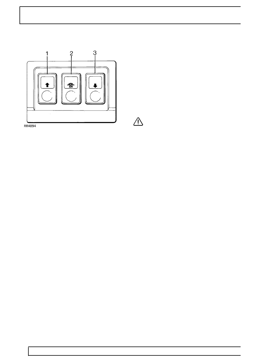
Control switches
Mounted on the lower dash, three control switches are
arranged thus:
1 - Raise - momentary touch switch.
2 - Inhibit - self latching switch, when switched on the
vehicle will remain at standard ride height. This
position is used when the automatic height adjustment
is not required i.e. when towing. Self levelling will
continue to function.
3 - Lower - momentary touch switch.
The switches incorporate a warning lamp. When
engine is started all three warning lamps will illuminate
for three seconds as part of bulb check. The switches
are illuminated when the vehicle lights are on.
The following components are contained in the AIR
SUPPLY UNIT mounted on the RH side of the
chassis:
AIR COMPRESSOR
AIR DRIER
VALVE BLOCK
Air compressor
The air compressor provides system pressure. A
thermal switch is incorporated which switches off the
compressor relay ground at 130
°
C. The compressor
has an air intake silencer mounted behind rear mud
flap. The air intake filter is located adjacent to the fuel
filler flap. The filter is renewed every 40,000
kms/24,000 miles/24 months. (30,000 miles USA).
Air drier
The air drier is connected into the air line between
compressor and reservoir. It removes moisture from
pressurised air entering the system. When air is
exhausted from the system it passes through the drier
in the opposite direction. The air drier is regenerative
in that air absorbs moisture in the drier and expels it to
the atmosphere.
The air drier unit is non-serviceable, designed to last
the life of the vehicle. However if water is found in the
system when reservoir drain plug is removed, the air
drier must be changed.
CAUTION: If the air drier is removed from
the vehicle the ports must be plugged to
prevent moisture ingress.
Valve block
The valve block controls the direction of air flow. Air
flow to and from the air springs is controlled by six
solenoid operated valves, one for each air spring, one
inlet and one exhaust. A diaphragm valve operated by
the solenoid outlet valve ensures that all exhausted air
passes through the air drier. In response to signals by
the ECU, the valves allow high pressure air to flow in
or out of the air springs according to the need to
increase or decrease pressure. The valve block is
non-serviceable, in case of failure it must be replaced.
Non-return valves
The valve block contains three non-return valves.
NRV1 retains compressor air pressure by preventing
flow back to the compressor.
NRV2 prevents loss of pressure in the system if
reservoir pressure drops. It also ensures correct flow
through the inlet valve.
NRV3 ensures correct flow through the exhaust valve.
Reservoir
The 10 litre reservoir is mounted on the left hand side
of the chassis. One connection acts as inlet and outlet
to the rest of the system. It stores compressed air
between set pressure levels. The reservoir drain plug
requires removing every 40,000 kms/24,000 miles/24
months. (30,000 miles USA) to check for moisture in
the system.
See Adjustment, Air Reservoir - Drain