
5 L4-2.3L (2007)
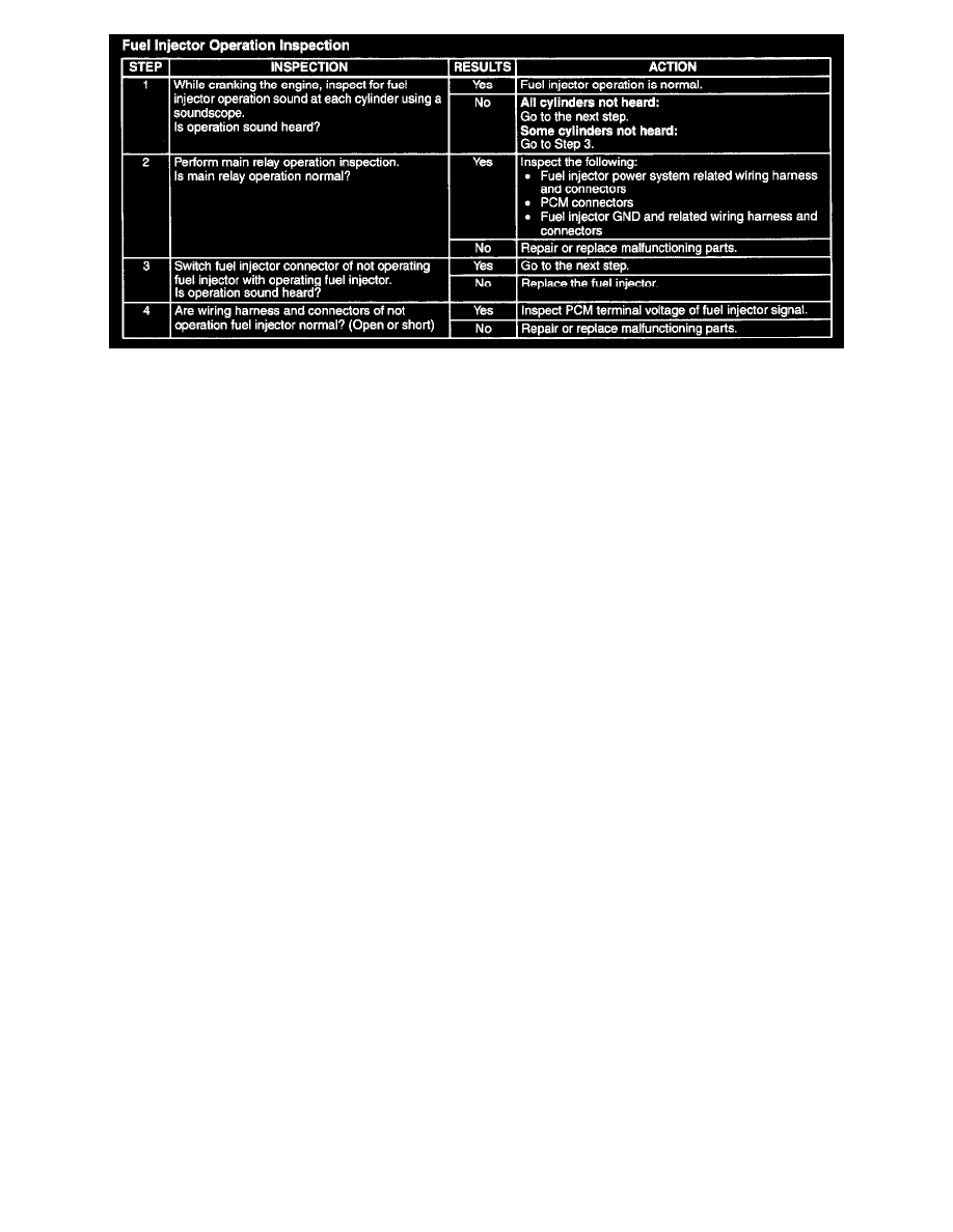
Step 1-Step 4
2
Inspect the variable tumble solenoid valve. (See VARIABLE TUMBLE SOLENOID VALVE INSPECTION[L3].)
-
If the variable tumble solenoid valve is not normal, replace the variable tumble solenoid valve.
-
If the variable tumble solenoid valve is normal, inspect the following:
-
Vacuum hose and vacuum chamber for looseness or damage
-
Shutter valve actuator (See VARIABLE TUMBLE SHUTTER VALVE ACTUATOR INSPECTION[L3].)
-
Shutter valve stuck open or closed
Fuel Cut Control System Inspection
1
Warm up engine and idle it.
2. Turn off the electrical loads and A/C switch.
3. Connect the M-MDS to the DLC-2.
4. Access RPM PID.
5. Listen for the fuel injector operation sound at all cylinders using the soundscope and monitor both PIDs while performing the following steps:
1
Depress the accelerator pedal and increase the engine speed to 4,000 rpm.
2
Quickly release the accelerator pedal (brake pedal is not depressed) and verify that the fuel injector operation sound stops, and starts again
when the engine speed drops below 2,200 rpm.
-
If not as specified, inspect the following:
-
ECT sensor and related wiring harness (See ENGINE COOLANT TEMPERATURE (ECT) SENSOR INSPECTION [L3]). See:
Coolant Temperature Sensor/Switch (For Computer)/Testing and Inspection
-
Neutral/clutch pedal position switch and related wiring harness (MTX) (See CLUTCH PEDAL POSITION (CPP) SWITCH
INSPECTION[L3]). See: Clutch Switch/Testing and Inspection
-
TR switch and related wiring harness (ATX) (See TRANSAXLE RANGE (TR) SWITCH INSPECTION[FN4A-EL].)
Fuel Pump Operation Inspection
1. Remove the fuel-filler cap.
2. Turn the ignition switch to the ON position.
3. Turn the fuel pump relay from off to on using the FP PID and inspect if the operation sound is heard.
-
If no operation sounds is heard, proceed to next step.
4. Measure voltage at wiring harness side fuel pump connector terminal A.
Specification
B+ (Ignition switch at on)
-
If the voltage is as specified, inspect the following:
-
Fuel pump continuity
-
Fuel pump GND
-
Wiring harness between fuel pump relay and PCM terminal 1AR (with immobilizer system), 1AO (without immobilizer system)
-
If not as specified, inspect the following:
-
Fuel pump relay
-
Wiring harness connector (Main relay - fuel pump relay - fuel pump.)
Fuel Pump Control System Inspection
1. Crank the engine and verify that fuel pump relay operation sound is heard.