
Mazdaspeed6 L4-2.3L Turbo (2006)
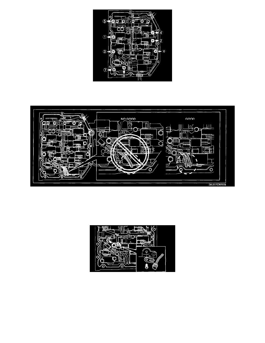
4. Tighten the bolts in the order shown in the figure.
Tightening torque 8 - 12 Nm (82 - 122 kgf-cm, 72 - 105 inch lbs.)
5. Install the connector of the VSS and input/turbine speed sensor to the solenoid clamp.
Caution:
^
If the control valve body cover Is installed with the wiring harnesses overlapped, the wiring harnesses may be pinched between the cover and
valve body causing the wiring harnesses to be damaged. Therefore, verify that the wiring harnesses are not overlapped when installing the
control valve body cover.
6. Apply ATF to a new O-ring and install it on the TFT sensor.
7. Install the TFT sensor with the lock plate and a bolt to the control valve body component as shown in the figure.
Tightening torque 8 - 12 Nm (82 - 122 kgf-cm, 72 - 105 inch lbs.)
8. Connect the solenoid connectors, VSS connector and the input/turbine speed sensor connector.