
RX7 2RTR-1146cc 70 (1982)
Engine Control Module: Testing and Inspection
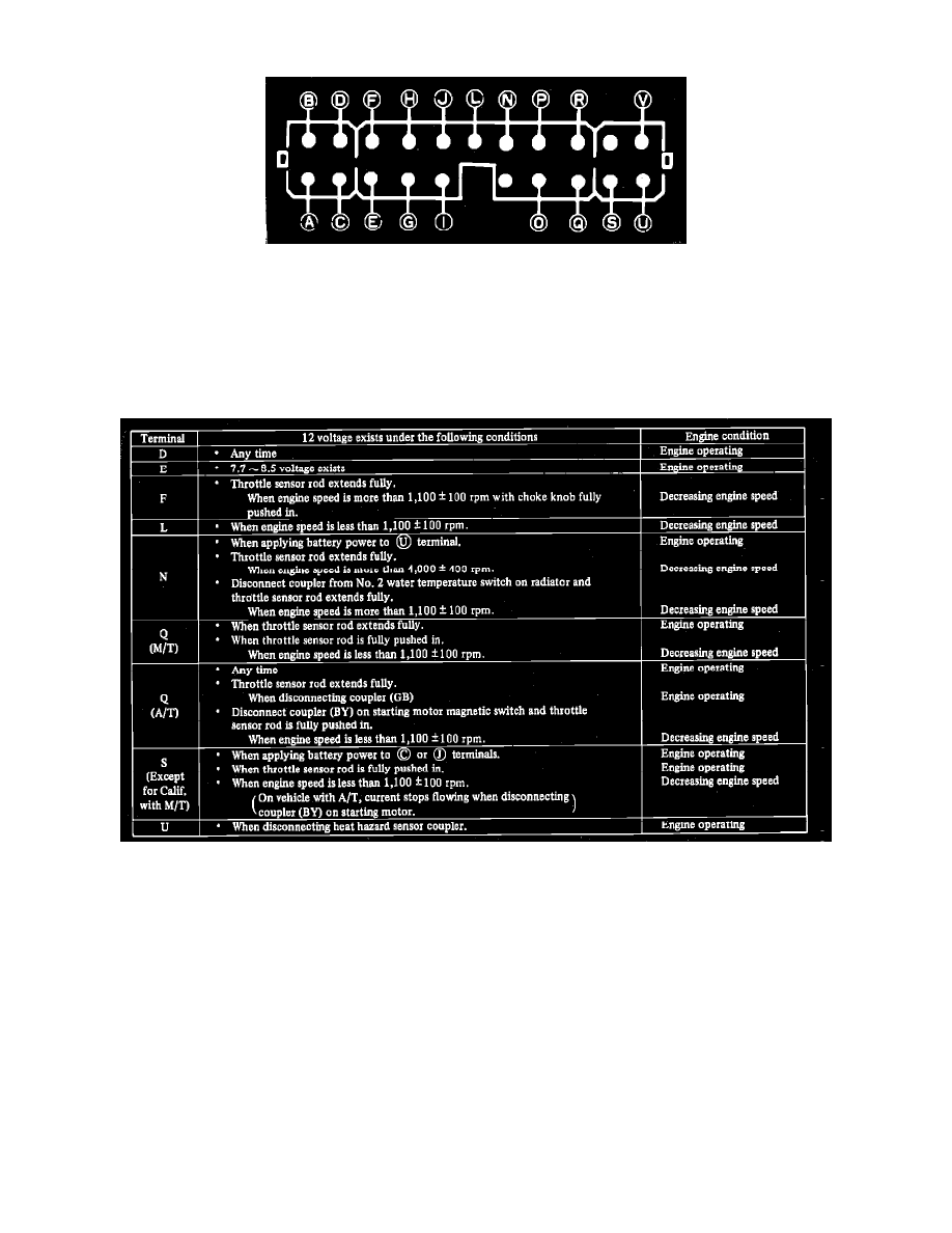
Fig. 22 Engine control unit terminal identification
1.
Start engine and allow to reach normal operating temperature.
2.
Check control unit fuse. If fuse has blown, replace fuse.
3.
Operate engine at idle and using a suitable voltmeter, ensure current flows to terminals (B), (J), (R) and (0), Fig 22.
4.
With engine idling, check voltage at terminal (A). Voltage should be 3-8 volts.
5.
On vehicles equipped with automatic transmission, position shift lever in "Park" position, then disconnect electrical connector from carburetor
throttle sensor and connect another throttle sensor to connector.
Fig. 23 Engine control unit testing procedure chart
6.
Connect voltmeter negative lead to (P) terminal, then with engine operating as shown in chart Fig. 23, connect positive lead to terminals indicated
and check for voltage specified. If voltage is not as specified, check circuit of terminal being tested. If circuit is normal, replace engine control unit