
RX7 2RTR-1146cc 70 (1982)
Choke Relay: Testing and Inspection
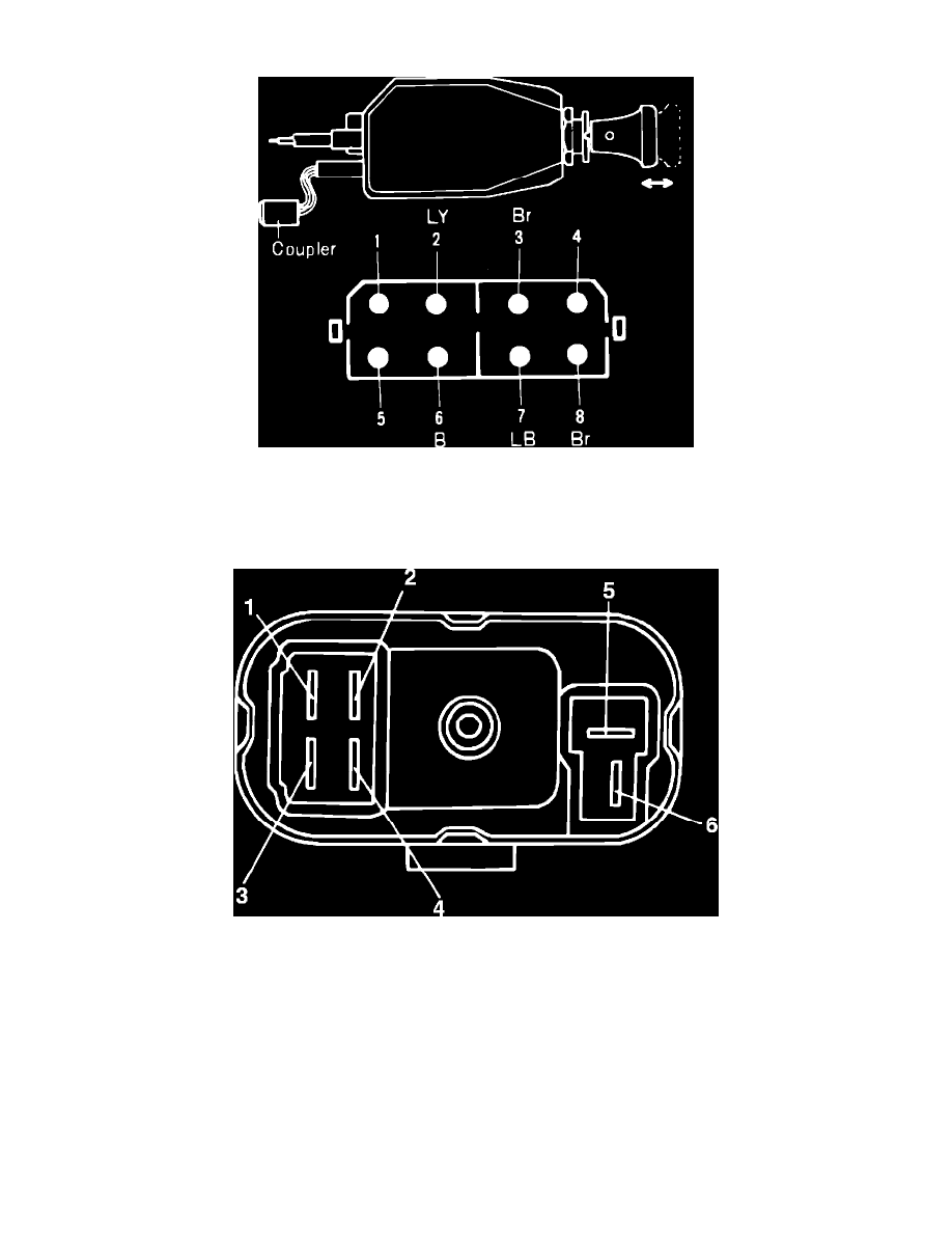
Fig. 26 Full choke switch, choke switch and magnet terminal identification
1.
Disconnect coupler from choke relay.
2.
With no power applied to relay terminals 5 and 6, Fig. 26, check for continuity between terminals 1 and 2. No continuity should exist between
terminals 3 and 4.
Fig. 27 Choke relay terminal identification
3.
With battery positive lead connected to terminal 6 and negative lead connected to terminal 5, check for continuity between terminals 3 and 4, Fig.
27. No continuity should exist between terminals 1 and 2.