
Capri V8-302 5.0L (1982)
Valve Clearance: Adjustments
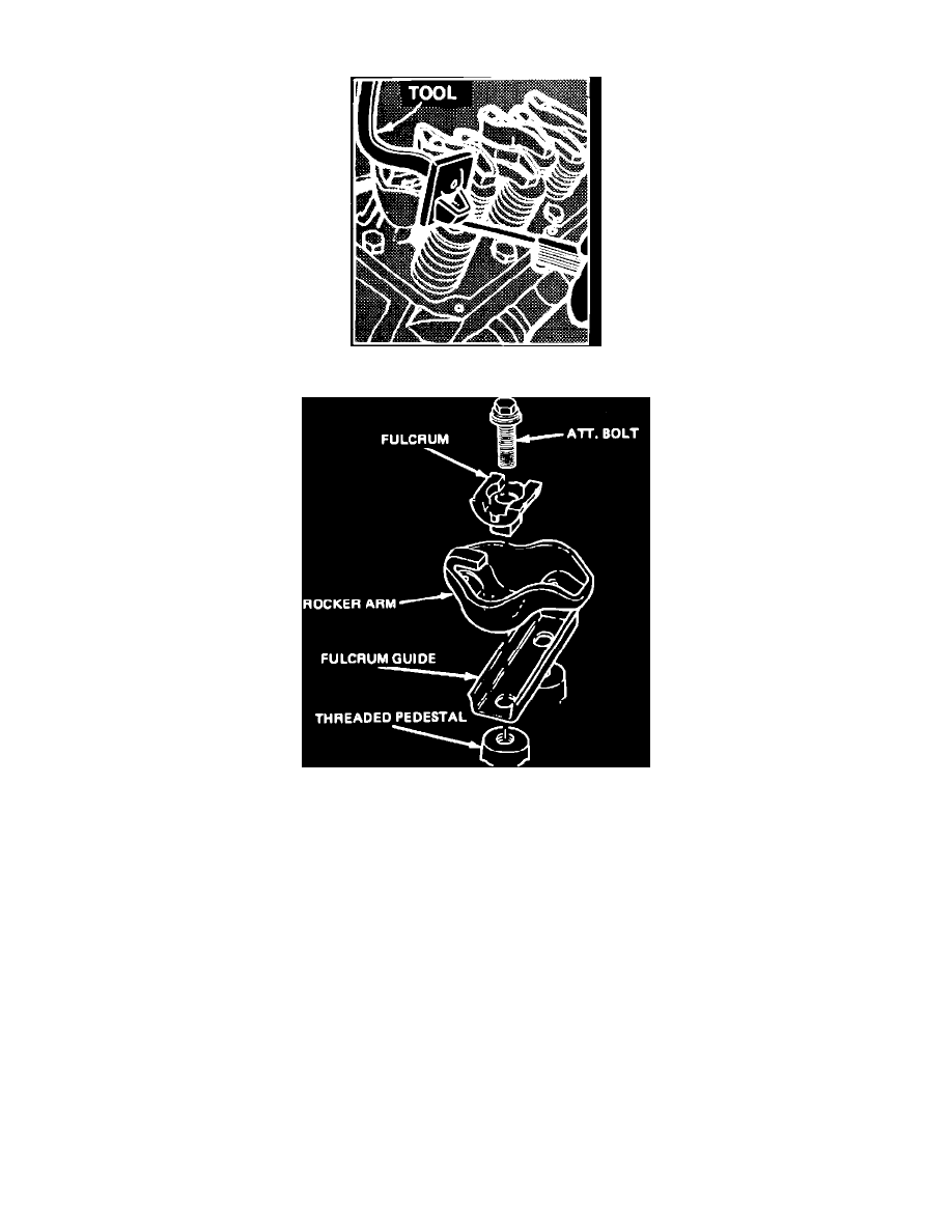
Fig. 6 Valve Clearance Adjustment
Fig. 5 Rocker Arm
V8 ENGINES
For these engines, a .060 inch longer or a .060 inch shorter pushrod is available to provide a means of compensating for dimensional changes in the
valve train and rocker arm. If the clearance is less than the minimum, the .060 inch shorter pushrod should be used. If clearance is more than the
maximum the .060 inch longer pushrod should be used.
All engines use a bolt and fulcrum attachment, Fig. 19.
To check valve clearance, proceed as follows:
1.
Mark crankshaft pulley at three locations with number 1 location at TDC timing mark (end of compression stroke), number 2 location one half turn
(180°) clockwise from TDC and number 3 location three quarter turn clockwise (270°) from TDC.
2.
Turn the crankshaft to the number 1 location, then compress valve lifter using tool T71P-6513-A or equivalent, Fig. 18, and check the clearance
on the following valves:
a. V8-255, 302 (Exc. H.O.): intake Nos. 1, 7 and 8; exhaust Nos. 1, 4 and 5.
b. V8-302 (H.O.): intake Nos. 1, 4 and 8; exhaust Nos. 1, 3 and 7.
3.
Turn the crankshaft to the number 2 location, then compress valve lifter using tool T71P-6513-A or equivalent, Fig. 18, and check the clearance
on the following valves:
a. V8-255, 302 (Exc. H.O.): intake Nos. 4 and 5; exhaust Nos. 2 and 6.
b. V8-302 (H.O.): intake Nos. 3 and 7; exhaust Nos. 2 and 6.
4.
Turn the crankshaft to the number 3 location, then compress valve lifter using tool T71P-6513-A or equivalent, Fig. 18, and check the clearance
on the following valves:
a. V8-255, 302 (Exc. H.O.): intake Nos. 2, 3 and 6; exhaust Nos. 3, 7 and 8.
b. V8-302 (H.O.): intake Nos. 2, 5 and 6; exhaust Nos. 4, 5 and 8.