
Mariner 2WD V6-3.0L VIN 1 (2006)
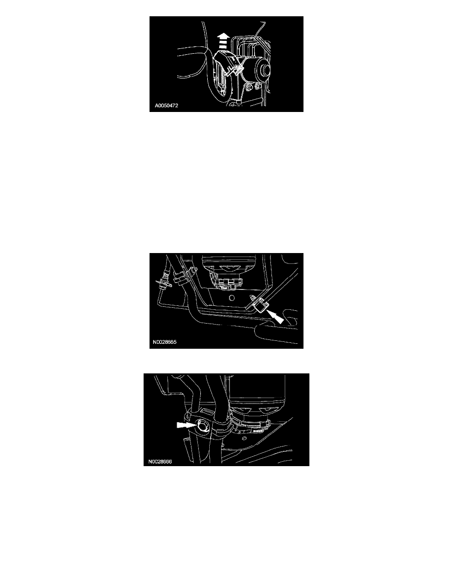
6. Disconnect the electrical connector by rotating the protective cover.
7. Release the clamp and remove the brake fluid low pressure feed hose.
8. Release the clamp and remove the brake fluid low pressure return hose.
9. NOTE: Note the order of the brake lines.
Disconnect the brake line-to-HCU fittings (10 mm).
^
To install, tighten to 18 Nm (13 ft. lbs.).
10. NOTE: Note the order of the brake lines.
Disconnect the brake line-to-HCU fittings (12 mm).
^
To install, tighten to 18 Nm (13 ft. lbs.).
11. Remove the 3 HCU bracket-to-frame bolts.
^
To install, tighten to 23 Nm (17 ft. lbs.).
12. Disconnect the brake line from the routing clip located at the bottom of the HCU bracket.
13. Remove the A/C line routing to HCU bracket bolt.
14. Remove the HCU assembly.
15. NOTE: When installing, use a suitable lubricant.
Remove the 3 HCU grommets.
16. NOTE: Use care not to cross the lines during installation. If the brake lines are crossed, the ABS module will set DTC(s) during an ABS event.
To install, reverse the removal procedure.
^
Bleed the brake system.