
Milan FWD V6-3.0L (2010)
-
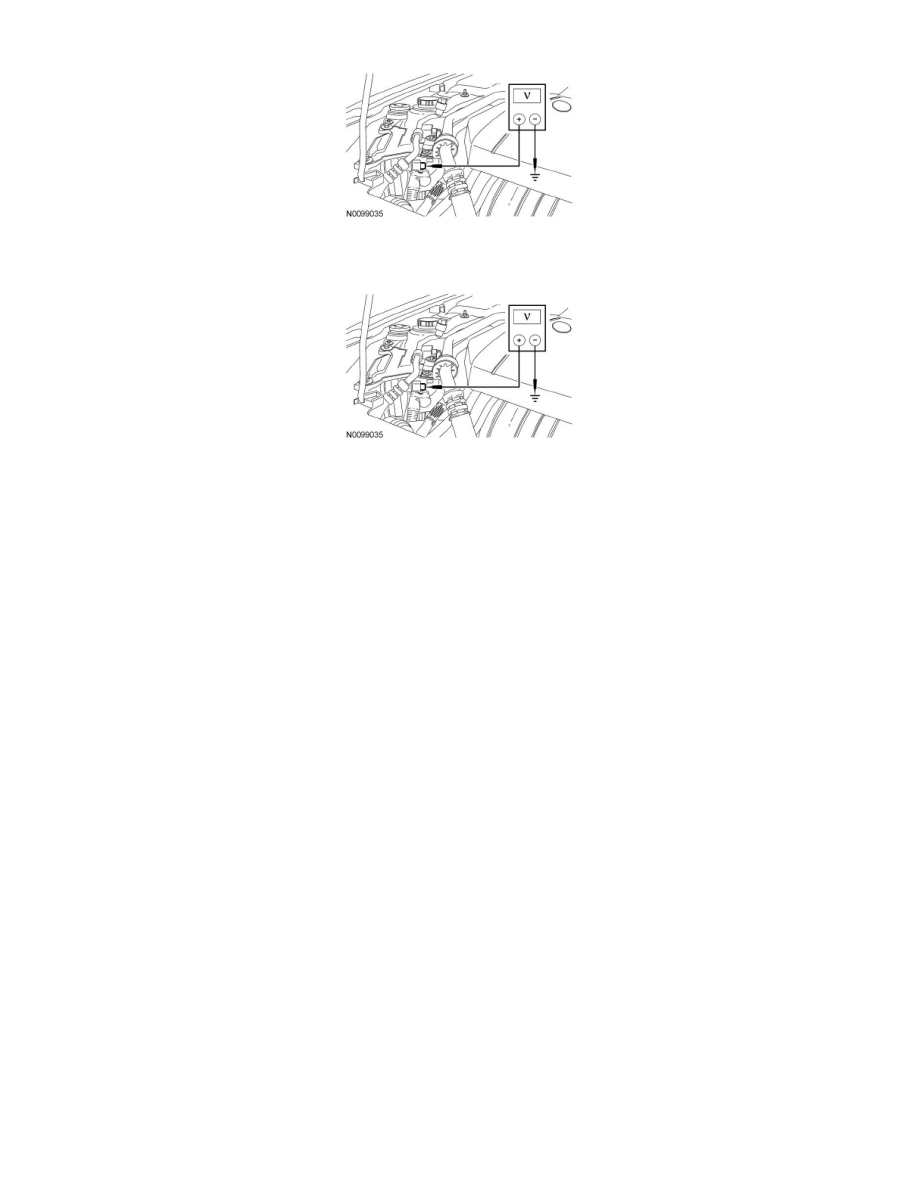
Measure the voltage between DC/DC C1457B, B+ terminal and ground.
-
Start the engine.
-
Measure the voltage between DC/DC C1457B, B+ terminal and ground.
-
Did the voltage increase with the ignition ON?
Yes
GO to A3.
No
GO to A2.
-------------------------------------------------
A2 CHECK THE DC TO DC VOLTAGE CONVERTER STATUS (EnableStat) PID
-
Connect the scan tool.
-
Enter the following diagnostic mode on the scan tool: DataLogger - DC/DC.
-
Monitor the EnableStat PID.
-
Does the PID read Enable?
Yes
GO to A4.
No
CARRY OUT self-test of the PCM and Battery Energy Control Module (BECM). REFER to Computers and Control Systems Information and Hybrid
Drive Systems for further diagnosis.
-------------------------------------------------
A3 CHECK THE PCM RELAY CONTROL INPUT TO THE DC/DC
-
Ignition OFF.
-
Disconnect: DC/DC C1457D.
-
Start the engine.
-
Measure the voltage between DC/DC C1457D-7, circuit CBK03 (GY), harness side and ground.