
Mountaineer 2WD V8-4.6L (2010)
Removal
NOTICE: If the Smart Junction Box (SJB) is dropped, damage to the internal components may occur. A new SJB must be installed.
NOTICE: Electronic modules are sensitive to static electrical charges. If exposed to these charges, damage may result.
NOTE: Prior to the replacement of the module, it is necessary to upload the module configuration information into the appropriate scan tool. This
information must be downloaded into the new module after installation. For additional information, refer to Information Bus.
NOTE: The Tire Pressure Monitoring System (TPMS) functionality is integral to the SJB. The steps in this procedure are critical to restoring the
vehicle security and the TPMS to normal operation. A new SJB is delivered in a manufacturing mode with 6 pre-set DTCs related to the TPMS. To clear
the DTCs, successful configuration of the SJB must occur, followed by successful TPMS sensor training, and a successful self-test, including clearing of
the DTCs. The DTCs are as follows:
-
B2477 (Module Configuration Failure)
-
B2868 (Left Front Tire Pressure Sensor Fault)
-
B2869 (Right Front Tire Pressure Sensor Fault)
-
B2870 (Right Rear Tire Pressure Sensor Fault)
-
B2871 (Left Rear Tire Pressure Sensor Fault)
-
C2780 (ECU in Manufacturer Sub-State)
1. NOTE: This step is necessary only if the SJB is being replaced.
Upload the module configuration information from the SJB. For additional information, refer to Information Bus.
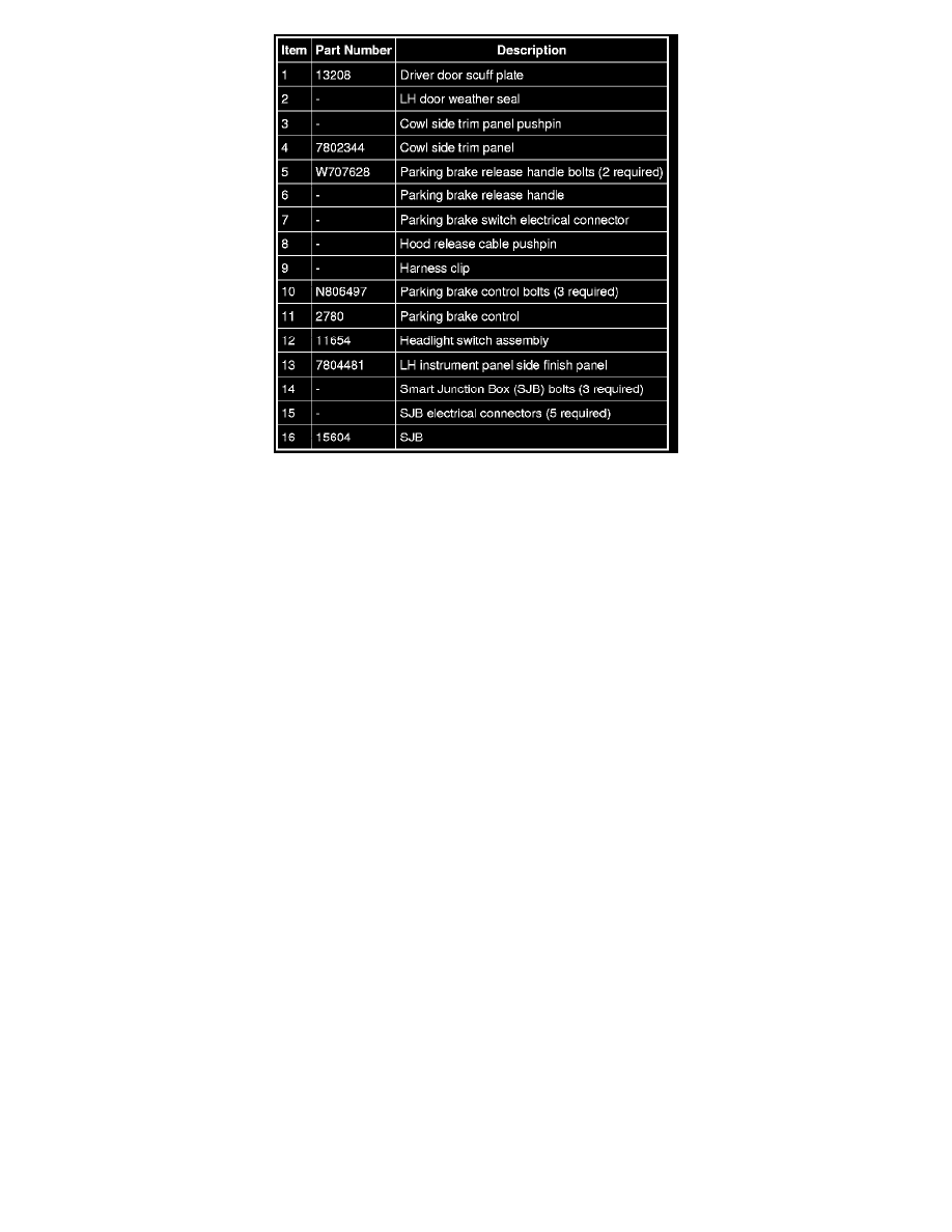
2. Remove the driver door scuff plate.
3. Position the LH door opening weather seal aside.
4. NOTE: While pulling the trim panel rearward, pull the hood release lever rearward in order for the release lever to slide through the trim panel.
Remove the pushpin and the cowl side trim panel.
5. Remove the 2 bolts and the parking brake release handle.
6. Disconnect the parking brake switch electrical connector.
7. Release the hood release cable pushpin from the parking brake control bracket.
8. Release the harness clip from the parking brake cable housing.
9. NOTE: Rotating the parking brake control counterclockwise allows enough access to clear the instrument panel reinforcement.