
Sable V6-232 3.8L (1988)
Radiator Cooling Fan Motor Relay: Description and Operation
The electro-drive cooling fan system consists of a two-speed fan on all 2.5L, 3.0L and 3.8L engines with ATX or a one-speed fan on 2.5L engines
with MTX, and an electric motor attached to a fan shroud located behind the radiator. The electro-drive cooling fan is wired to operate only when the
ignition switch is in the RUN position, thereby preventing cooling fan operation after the ignition switch is turned to the OFF position.
WARNING: DISCONNECT THE COOLING FAN PRIOR TO PERFORMING ANY UNDERHOOD SERVICE SINCE THE FAN COULD
CYCLE IF THE IGNITION SWITCH IS LEFT IN THE ON POSITION EVEN THOUGH THE ENGINE IS NOT RUNNING.
The cooling fan is controlled during vehicle operation by the Integrated Control Module assembly and EEC-IV module, which will energize the
cooling fan under the following conditions:
Cooling fan is turned on at low speed if:
a. Engine temperature is higher than normal. (Fan starts running at 102°C (215°F), and stops running at 99°C (210°F)).
b. A/C is on and vehicle speed does not provide enough natural airflow (Fan starts running at speeds at or below 69 km/h (43 mph) and stops
running at 77 km/h (48 mph)).
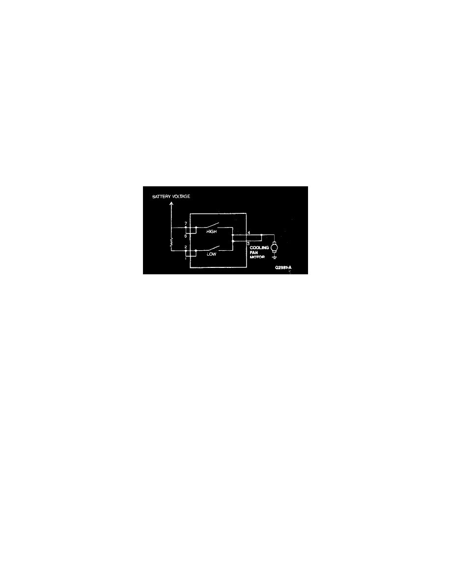
low speed cooling fan motor operation is achieved by using a dropping resistor in series with the motor.
Cooling Fan Motor Circuit Diagram with Motor
-
Cooling fan will run at high speed if (except 2.5L MTX):
a. Engine temperature is higher than desirable and fan has been operating at low speed. Fan starts running at high speed at 110°C (230°F),
and stops running at 107°C (224°F)).
-
Cooling Fan will not turn off (providing engine coolant temperature is not too high) if:
a. Driver demand is high (WOT mode).
b. A/C clutch is not cycling rapidly.
Several different integrated controller modules are available depending on application. Proper operation of the system cannot be obtained unless the
correct integrated controller module is used.