
Sable V6-232 3.8L (1988)
Ignition Control Module: Description and Operation
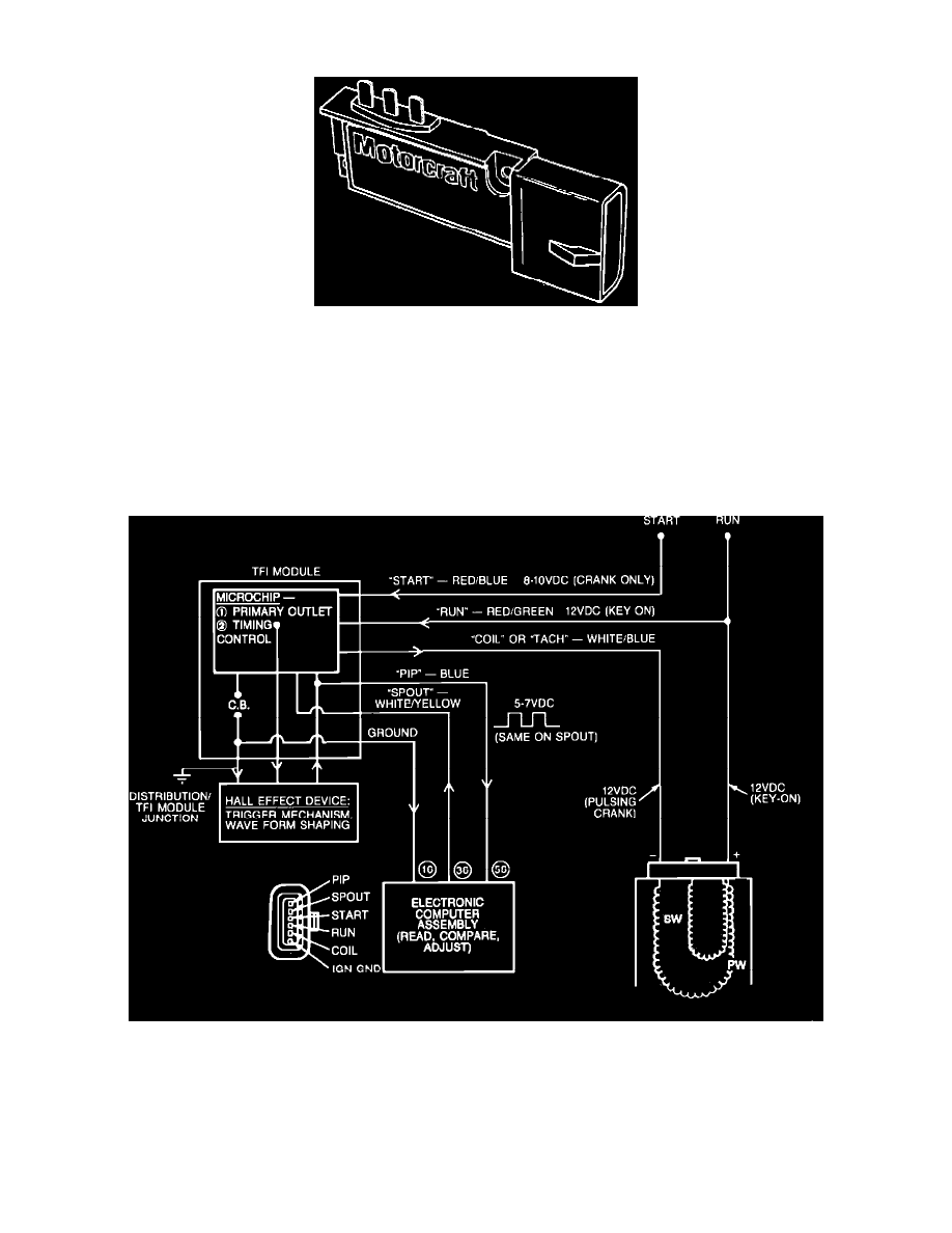
Thick Film Ignition Module
The TFI IV ignition module, Fig. 14, has six connector pins at the wiring harness that supplies the following signals:
Run
Crank (start)
Tach (coil)
PIP (crankshaft position to ECA)
Spark output (SPOUT from ECA)
Internal ground from the ECA to the distributor
Ignition System
The TFI IV module supplies the spark to the distributor through the ignition coil and calculates the duration. It receives its control signal from the ECA
(SPOUT) Fig. 29.
NOTE: Some later models use a remote module (Closed Bowl Distributors/CBD). It is located in the engine compartment (Refer to
"COMPONENT LOCATIONS"). The operation is essentially the same with the exception of the CBD has a wiring harness between the
ignition module and the distributor.