
Villager V6-181 3.0L SOHC VIN 1 EFI (1997)
Wheels: Component Tests and General Diagnostics
Leaks
Slow air leaks may occur in cast aluminum wheels because of porous wheel castings. Perform the following procedure to repair the air leak:
1. Remove the wheel and tire assembly and inspect the wheel for structural damage. If the wheel is damaged, replace it.
2. If the wheel is not damaged, check for air leaks (with the tire mounted on the wheel) using a water bath or an equivalent method. Mark the air leak
location.
3. Dismount the tire.
4. Remove the air valve if it is near the repair area.
5. Thoroughly clean the leaking area (on the tire side of the wheel) using 80 grit sandpaper. Be sure to scrub the surface to improve sealant adhesion.
Prepare an adequate area around the leak to ensure complete leak coverage.
6. Use a clean rag to remove all of the sanding dust.
7. Using either a propane torch or Rotunda Heat Gun 107-R0301 or equivalent, heat the prepared area of the wheel.
CAUTION: Do not use an oxyacetylene torch to perform the next step. Apply only enough heat to melt the sealant.
NOTE: The repair is most effective when the heat is applied to the brake side of the wheel, and the sealant is melted by the heated aluminum on
the tire side of the wheel.
8. Apply a liberal amount of Aluminum Wheel Repair Compound E7AZ-19554-A or equivalent meeting Ford specification ESA-M4G280-A over
the prepared area using a wiping motion to ensure complete leak coverage.
9. Allow the wheel to cool until it can be handled safely.
10. Mount the tire and inflate it to the recommended pressure.
11. Check that the leak is repaired using the procedure in step 2. If the leak is still present, replace the wheel.
12. Balance the wheel and tire assembly, then install it on the vehicle.
Runout
DESCRIPTION
Excessive radial and lateral runout of a wheel and tire assembly can cause roughness, vibration, wheel tramp, tire wear, and steering wheel tremor.
Before checking runout, and to avoid false readings caused by temporary flat spots in the tires, check runout only after the vehicle has been driven far
enough to warm the tires.
Measure the extent of the runout with Rotunda Radial Runout Gauge. All measurements are made on the vehicle with the tires inflated to
recommended inflation pressures and with the front wheel bearings adjusted to specifications.
TIRE RUNOUT
Using Rotunda Radial Runout Gauge 007-0056A, measure radial runout of the tire at the center and outside ribs of the tread face. Mark the high
points of radial runout for future reference. On tires, radial runout should not exceed 1.78 mm (0.070 inch).
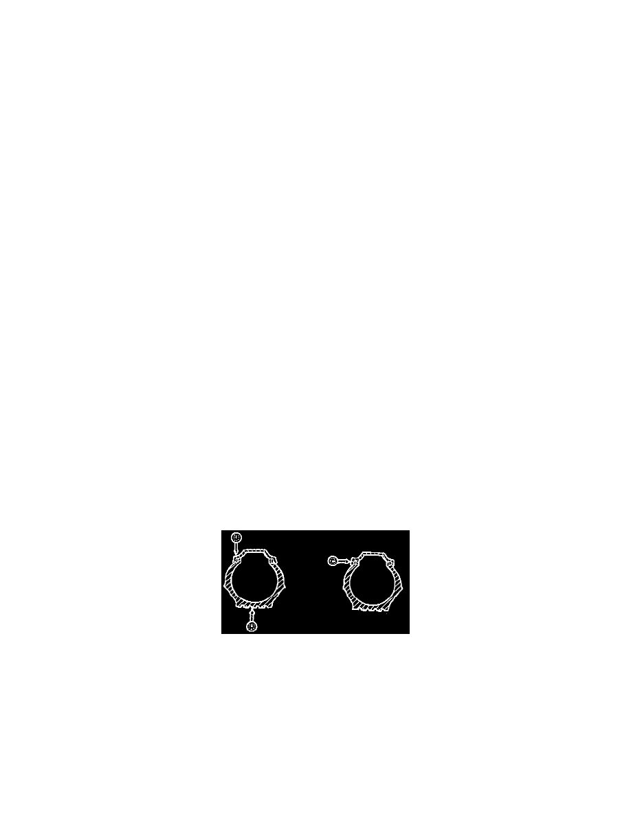
WHEEL RUNOUT
Measure radial and lateral wheel runout at the positions shown in the illustration. Runout should not exceed specifications in either position.
Runout should not exceed the values shown in the table below.
Aluminum Wheels
Max. Radial Runout: 0.3 mm (0.012 inch)
Max. Lateral Runout: 0.3 mm (0.012 inch)
Steel Wheels
Max. Radial Runout: 0.8 mm (0.031 inch)
Max. Lateral Runout: 0.8 mm (0.031 inch)