
Galant L4-1997cc 2.0L SOHC 16 Valve (1993)
Less Electronically Controlled Suspension
1. Raise and support vehicle.
Fig. 10 Stabilizer Bar Link Bolt Protrusion
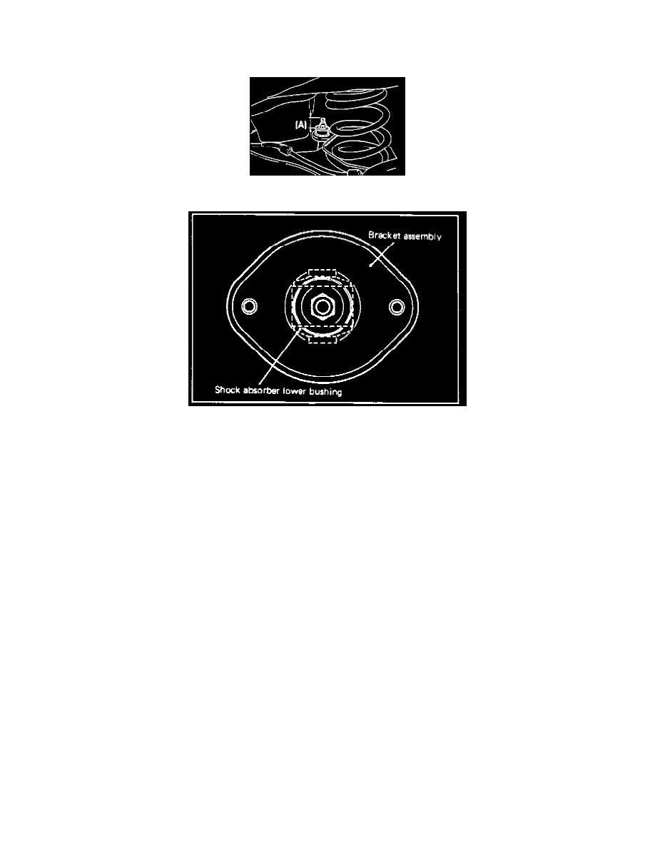
Fig. 8 Bracket Assembly Installation
2. Position jack under torsion axle and arm assembly, Fig. 7 and 8.
3. Remove shock absorber cap, shock absorber upper, then lower attaching nuts.
4. Remove shock absorber assembly from torsion axle and arm assembly.
5. Compress coil spring, then, while holding piston rod, remove piston rod attaching nut.
6. Remove washer, upper bushing (A), bracket, spring pad, upper bushing (B), collar, cup, dust cover, rubber bumper and coil spring from shock
absorber.
7. Inspect rubber parts and coil springs for cracks, damage or deterioration and replace as necessary. If coil spring replacement is necessary, be
sure to use spring having the correct identification marks.
8. Fully compress coil spring, then install spring into shock absorber.
9. Install dust cover on cup assembly.
10. Extend piston rod as far as possible, then install rubber bumper, cup assembly, collar, upper bushing (B), spring pad, bracket assembly, upper
bushing (A) and washer.
11. Position bracket assembly as shown, Fig. 8, tighten piston rod attaching nut to specification, then remove spring compressor.
12. Install shock absorber assembly in torsion axle and arm assembly. Tighten lower attaching bolts to specification.
13. Install cap, then the shock absorber attaching nuts. Tighten upper attaching bolts to specification.
14. Install trunk compartment front trim, then remove jack from torsion axle and arm assembly.
15. Install rear wheels.