
Galant L4-1997cc 2.0L SOHC 16 Valve (1993)
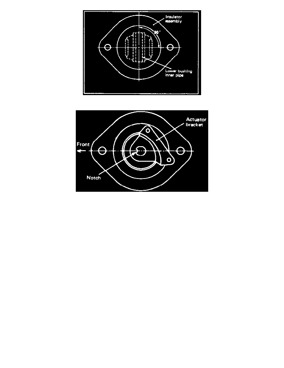
Fig. 10 Bracket Assembly Installation
Fig. 11 Piston Rod Alignment
1. Remove dust cover, Fig. 9 through 11, then disconnect and cap air tube from shock absorber. Use caution not to bend air tube.
2. Remove actuator from actuator bracket.
3. Remove adapter and snap ring, then the joint assembly from piston rod.
4. Remove O-ring and actuator bracket from piston rod.
5. Raise and support vehicle, then remove rear wheels.
6. Remove shock absorber assembly from torsion axle and arm assembly.
7. Remove shock absorber attaching nuts, then the shock absorber assembly from wheel housing. Use caution not to damage piston rod.
8. Check shock absorber assembly for air leaks as follows:
a. Install joint assembly to shock absorber assembly and secure with snap ring.
b. Using air compressor for air supply, disconnect white air tube from solenoid valve, then connect tool No. MB991075, or equivalent, and inject
71 psi of air.
c. Submerse shock absorber assembly into a water tank and check for air leakage.
d. If air leakage is present, check sub-tank, O-ring and shock absorber assembly in that order. Repair as required.
9. Remove insulator attaching nut, then the insulator assembly, sub-tank, coil spring and lower spring pad.
10. Remove O-ring from sub-tank.
11. Check rubber parts, sub-tank and coil spring for damage, deterioration, deformation or cracks. Repair as required.
12. Install lower spring pad and coil spring on shock absorber. When replacing coil spring, note that the left and right identification marks are
different.
13. Coat O-ring with specified grease, then install O-ring in sub-tank.
14. Install sub-tank, then the insulator assembly while temporarily tightening nut so installation angle of insulator assembly and lower bushing inner
pipe is as shown, Fig. 11.
15. Recheck shock absorber assembly for air leaks. Refer to step 9.
16. Install shock absorber assembly, then lower vehicle as slow as possible to prevent damaging or deforming diaphragm.
17. Position piston rod notch as shown, Fig. 11, hold end of piston rod using a wrench, then tighten insulator assembly attaching nuts to specification.
18. Install actuator bracket, then tighten to specification.
19. Install O-ring on piston rod, the joint assembly, then secure with snap ring.
20. Install adapter and actuator, then connect air tubes.
21. Start engine and check for air leaks, then install dust cover.