
Galant LS V6-3.0L SOHC (1999)
The rear door switch (LH) input signal should be able to be checked and the functions, which are described in the "Technical Description (comment),"
should work normally.
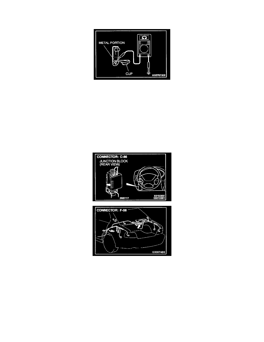
STEP 31. Check the rear door switch (RH) condition.
NOTE: The rear door switch (RH) is grounded to the vehicle body via its mounting screw.
Turn up the cup, and measure the resistance between the lower metal portion and the ground.
-
Should be less than 2 Ohms.
If open circuit, check the installation condition and correct it as necessary.
The rear door switch (RH) input signal should be able to be checked and the functions, which are described in the "Technical Description (comment),"
should work normally.
If less than 2 Ohms, go to Step 32.
STEP 32. Check the rear door switch (RH) connector F-08 and ETACS-ECU connector C-86 for damage.
If the rear door switch (RH) connector F-14 and ETACS-ECU connector C-86 are damaged, repair or replace them. Refer to Harness Connector
Inspection.
The rear door switch (RH) input signal should be able to be checked and the functions, which are described in the "Technical Description (comment),"
should work normally.
If the harness connectors are in good condition, go to Step 33.