
Montero Sport ES 4WD V6-3.0L SOHC (2002)
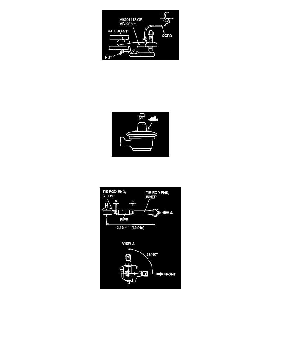
WARNING: Support special tool MB991113 or MB990635 with a cord, etc. to prevent it from coming off.
Use special tool MB991113 or MB990635 to disconnect the ball joint.
NOTE: Only loosen mounting nut, do not remove it from the ball joint.
INSTALLATION SERVICE POINTS
>>A<< RELAY ROD AND BALL JOINT CONNECTION
Apply the specified grease to the top (lip) of the dust cover.
Specified grease: Multipurpose grease SAE J310, NLGI No.2 or equivalent
>>B<< TIE ROD ASSEMBLY INSTALLATION
CAUTION: The outer end of the tie rod end has left thread.
1. Install the tie rod assembly so that the dimension is as shown in the illustration.
NOTE: The illustration at left shows the left side tie rod assembly. The right side tie rod assembly is symmetrical to the left side assembly.
2. Adjust the pipe so that the deference between dimensions (a) and (b) is 1.5 mm (0.059 inch) or less, and then temporarily tighten the lock nut.
NOTE: Fully tighten the lock nut after the tie rod assembly is installed to the body and the toe-in has been adjusted.
INSPECTION