
Pickup 4WD V6-2972cc 3.0L SOHC (1991)
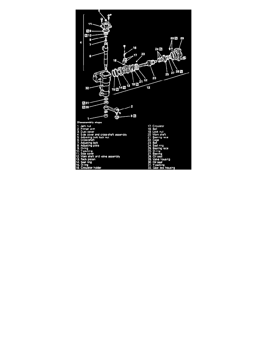
Fig. 28 Steering Gear. 1990-92 Montero
Disassemble power steering gear in numbered sequence shown in Figs. 27 and 28, noting the following:
1.
Remove pitman arm using Pitman arm removal tool No. MB990809-01 or equivalent.
2.
Position mainshaft and cross shaft in straight ahead position, then tap bottom of cross shaft lightly with a plastic hammer to remove the cross shaft
and side cover.
3.
Do not remove U-packing (except 1990-92 Montero) or Y-packing (1990-92 Montero) unless fluid is leaking from threads of adjusting bolt.
4.
On except 1990-92 Montero, proceed as follows:
a. Remove valve housing locknut using housing nut wrench tool No. MB990852-01 or equivalent.
b. Remove rack piston from mainshaft by turning it clockwise. Use care not to loose the 26 balls inside the rack piston.
c. Remove top cover and mainshaft by using spanner wrench tool No. MB990201-01 or equivalent, from the valve housing.
d. Install top cover on valve housing, then remove top cover bearing and seal using suitable bearing removal tool.
5.
On 1990-92 Montero, proceed as follows:
a. Remove rack piston from mainshaft by turning it counterclockwise. Use care not to loose the 26 balls inside the rack piston.
b. Remove locknut using spanner wrench tool No. MB991367 or equivalent.
c. Remove mainshaft while pressing bearing race so ball do not drop out.
d. Remove valve housing oil seal and bearing using a suitable bearing removal tool.
Assembly
Assemble power steering gear in reverse numbered sequence shown in Figs. 27 and 28, noting the following:
1.
Apply grease to bearing surface of side cover needle bearing and install the 33 rollers.
2.
Apply grease to bottom of side cover, then position new O-ring on the cover.
3.
Install adjusting bolt and plate into slot on top of cross shaft. Install plate with chamfered side toward cross shaft mating surface.
4.
Adjust cross shaft endplay to 0 -.002 inch, using spacers as necessary.
5.
Install side cover onto cross shaft, tighten with adjusting bolt, then tighten locknut temporarily.
6.
Apply thin coat of grease to gear housing U-packing and oil seal, then press them into housing using tools Nos. MB990938 and MB990926 or
equivalents.
7.
Apply thin coat of grease to lip of valve housing oil seal, then press it into housing.
8.
Press ball bearing into top cover, then install thrust plate, needle roller bearing and second thrust plate into cover. Install the thinner of the two
thrust plates on top cover side.
9.
Install, then temporarily tighten the top cover.