
Raider V6-3.7L SOHC (2006)
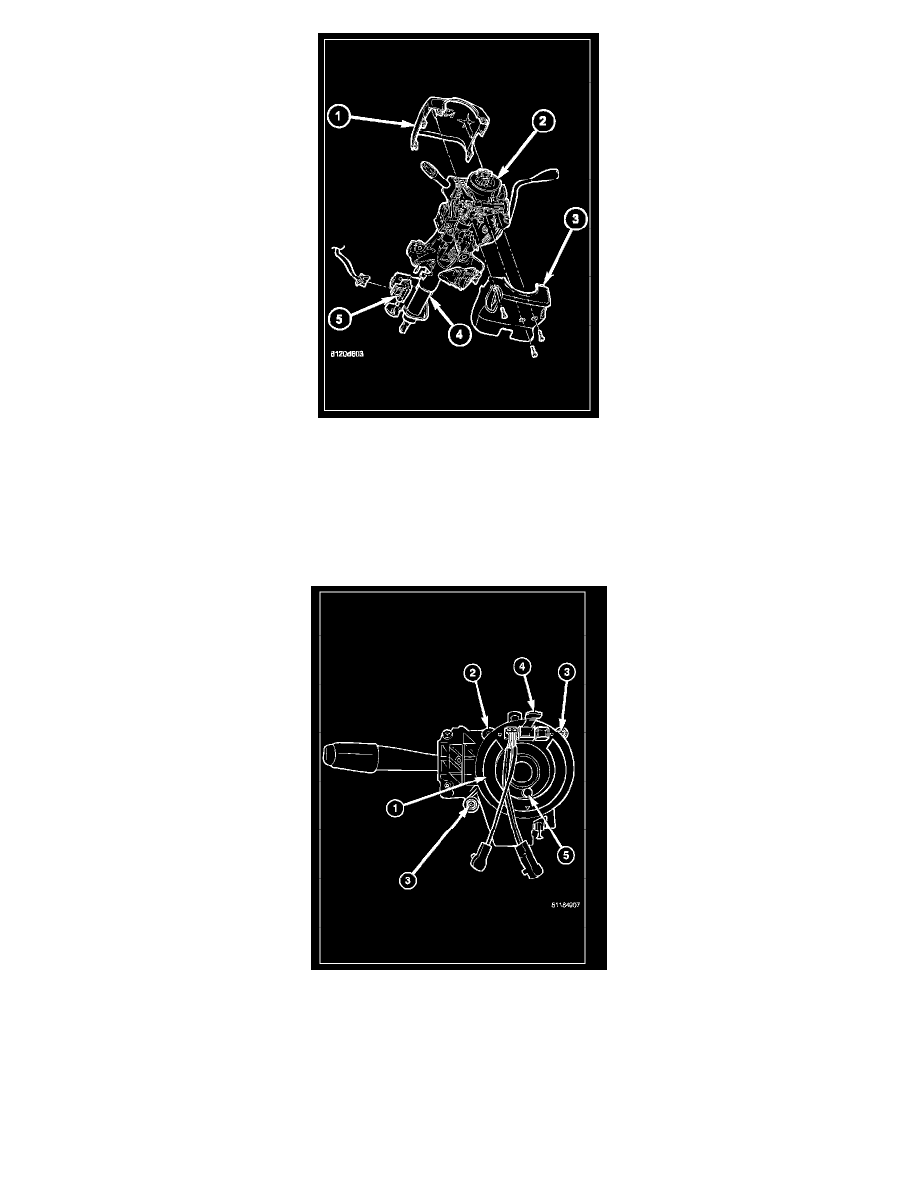
7. From below the steering column, remove the two outboard screws that secure the upper column shroud (1) to the lower shroud (3).
8. Using hand pressure, push gently inward on both sides of the upper shroud above the parting line of the lower shroud to release the snap features
that secure the two shroud halves to each other.
9. Remove the upper shroud from the lower shroud and the steering column.
10. Remove the one center screw that secures the lower shroud to the steering column (4).
11. Remove the lower shroud from the steering column.
12. Disconnect the two instrument panel wire harness connectors from the two connector receptacles located below the steering column on the back of
the clockspring housing.
13. Remove the two screws (3) that secure the clockspring to the multi-function switch mounting housing.
14. Remove the clockspring from the multi-function switch mounting housing. The clockspring cannot be repaired. It must be replaced if faulty or
damaged, or if the driver airbag has been deployed.
15. If the removed clockspring is to be reused, be certain to secure the clockspring rotor to the clockspring case to maintain clockspring centering until
it is reinstalled on the steering column. If clockspring centering is not maintained, the clockspring must be centered again before it is reinstalled.
INSTALLATION
WARNING: TO AVOID PERSONAL INJURY OR DEATH, ON VEHICLES EQUIPPED WITH AIRBAGS, DISABLE THE