
Raider 2WD V6-3.7L (2008)
reaction plate along with all the friction and steel discs.
20. Install the overdrive clutch pack (13) into the input clutch retainer. The overdrive steel separator plates can be identified by the lack of the
half-moon cuts in the locating tabs. The OD clutch discs can be identified by their radial groove pattern. The OD clutch discs can be identified by
their radial groove pattern.
21. Install the overdrive clutch wavy snap-ring (3) with the two tabbed ears into the OD/reverse piston.
22. Install the OD/reverse pressure plate (4) into the input clutch retainer. The pressure plate is non-directional.
23. Install the OD/reverse reaction plate flat snap-ring (6) into the OD/reverse piston.
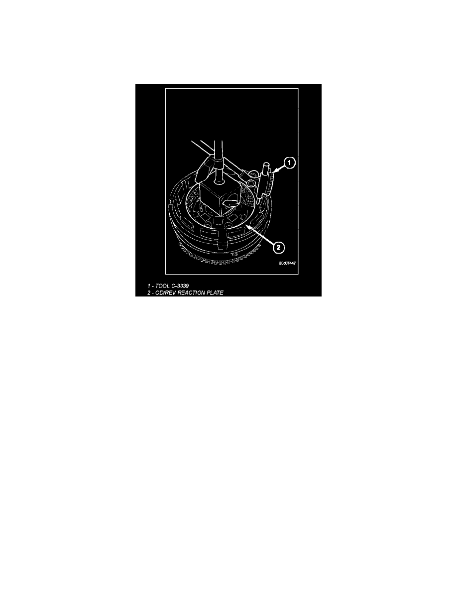
24. Mount a dial indicator C-3339A (1) on the input clutch hub and zero the indicator against the OD/reverse pressure plate (2). Apply 20 psi of air
pressure to the overdrive clutch and record the dial indicator reading. Measure and record OD clutch pack measurement in four (4) places, 90°
apart. Take average of four measurements and compare with OD clutch pack clearance specification. Verify that the clutch clearance is
1.103-1.856 mm (0.043-0.073 in.). The pressure plate is not selective. If the clutch clearance is not within specification, replace the pressure plate
along with all the friction and steel discs.
25. Install the reverse clutch pack into the input clutch retainer.
26. Install the reverse reaction plate into the input clutch retainer.
27. Install the reverse reaction plate selective snap-ring into the input clutch retainer.