
Cutlass Ciera Cruiser V6-3300 3.3L (1989)
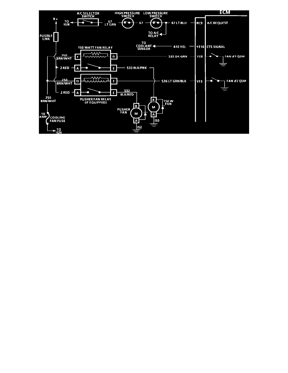
Chart C-12A,B,C Wiring Diagram
CIRCUIT DESCRIPTION:
Power for the coolant fan motor comes through the fusible link to terminal "A" on both relays. The relays are energized when current flows to ground
through the quad-driver module inside the ECM. The ECM controls the fan(s) after ignition "OFF" if coolant temperature is above value. The fan(s)
could run up[ to ten minutes.
The 150 Watt Fan Relay is energized by the ECM. The ECM energizes the relay through terminal "YE8" when the coolant temperature reaches 98~C
(208~F). The fan relay is also energized when refrigerant pressure reaches 150 psi (1034 kPa).
The optional Pusher Coolant Fan relay is energized by the ECM when the coolant temperature reaches 108~C (226~F) or refrigerant pressure reaches
245 psi (1896 kPa).
TEST DESCRIPTION:Numbers below refer to circled numbers on the diagnostic chart.
1.
Test light should be "ON" as the ignition switch is turned "ON." The "F" and "D" terminals are fed directly from the ignition.
2.
Test light should be "ON" as grounding the ALDL turns "ON" the QDM providing current flow to ground.
3.
Jumpering terminals "A" and "E" feeds the fan motor directly, and it should run.
4.
Test light should be "ON" as terminal "A" is connected directly to B+.
Part 3 of 3