
Conquest L4-2555cc 2.6L SOHC Turbo (1984)
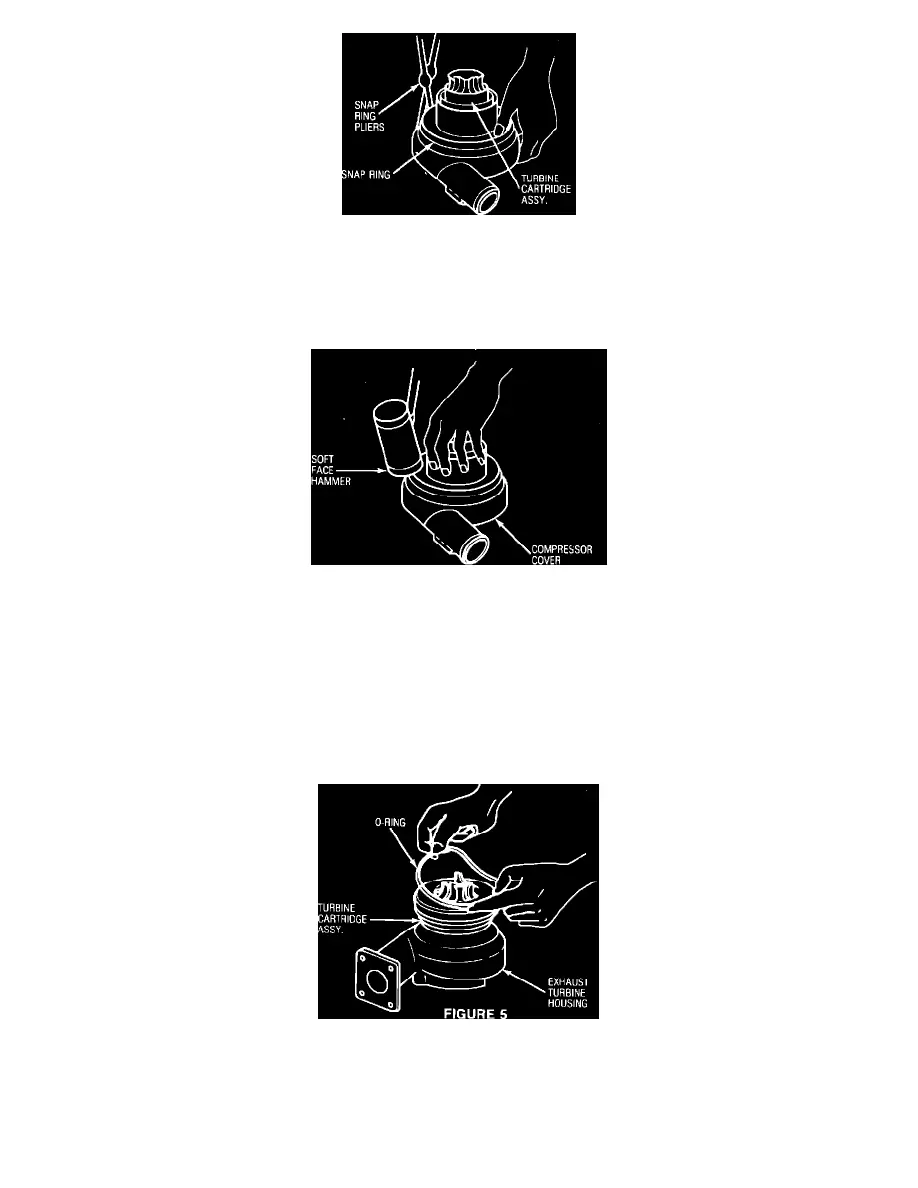
FIGURE 3
4.
With the compressor cover facing down, remove the snap ring retaining the compressor cover using snap ring pliers (Figure 3).
CAUTION:
WHEN REMOVING THE SNAP RING HOLD IT IN OPPOSITE THE PLIERS TO PREVENT IT JUMPING OUT
OF THE GROOVE SUDDENLY (FIGURE 3).
FIGURE 4
5.
Tap the compressor cover all around with a soft faced hammer (plastic or rubber) to separate the turbine cartridge from the compressor housing
(Figure 4).
NOTE:
THE TURBINE CARTRIDGE ASSEMBLY MAY BE SOMEWHAT DIFFICULT TO SEPARATE FROM THE COMPRESSOR
HOUSING BECAUSE OF THE O-RING INSTALLED ON THE OUTER EDGE OF THE CARTRIDGE.
ASSEMBLY
1.
Remove any carbon or fuel residue stains from the inner surfaces of the exhaust turbine and compressor housing with carburetor cleaner and a
brush. Blow dry and wipe off with a clean cloth.
FIGURE 5
2.
Install the turbine cartridge assembly to the exhaust turbine housing and install the coupling band loosely (Figure 5).
CAUTION:
BE CAREFUL NOT TO DAMAGE THE TURBINE BLADES DURING HANDLING AND ASSEMBLY OF THE
TURBINE CARTRIDGE.