
Grand Fury/Salon V8-318 5.2L VIN S 4-BBL (1984)
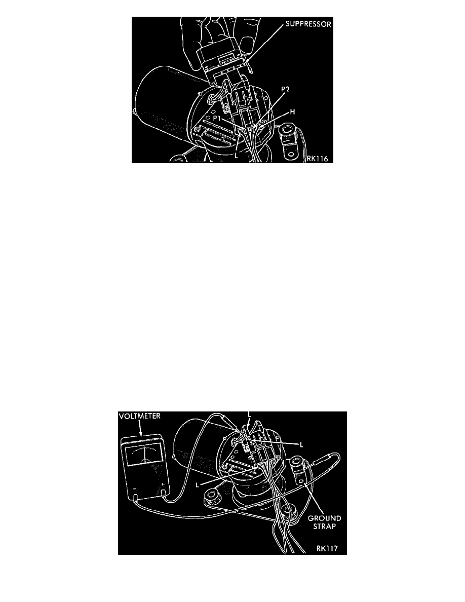
FIGURE 2 - WIPER MOTOR TERMINAL SUPPRESSOR
WIPER MOTOR WIRING CONNECTOR
To gain access to the wiper motor wiring terminals, remove terminal cover (Figure 1) or the suppressor (Figure 2) as required.
In the event that the wiper motor assembly is replaced, the terminal cover or suppressor must be reinstalled on the new unit.
Condition
Motor will not run in any switch position.
Procedure
1.
Check for a blown fuse in the fuse block.
a.
If fuse is good proceed to Step 2.
b.
If fuse is defective replace and check motor operation in all switch positions.
c.
If motor is still inoperative and the fuse does not blow proceed to Step 2.
d.
If replacement fuse blows proceed to Step 5.
2.
Place switch in low speed position.
3.
Listen to motor. If you cannot hear it running, proceed to Step 4. If you can hear it running, check motor output shaft. If output shaft is not turning,
replace motor assembly. If it is turning, drive link to output shaft or linkage is not properly connected. Replace worn parts and/or properly connect
drive link to the motor output shaft.
FIGURE 3 - VOLTMETER BETWEEN TERMINAL "L" & GROUND