
Grand Voyager V6-201 3.3L VIN R SMFI (1997)
Junction Block Terminal Call-Out With DRL
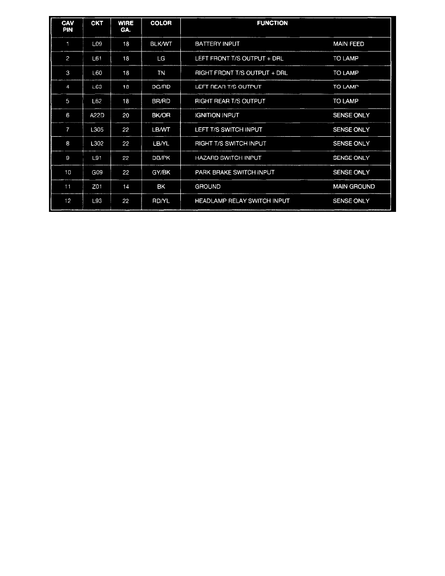
CIRCUIT OPERATION
The battery input (Pin 1), is brought into the Junction Block through the Electrical Distribution Wiring (EDW) harness through. It originates under
the hood in the Power Distribution Center (PDC) through a 20 ampere fuse at position 15 (5th position from the upper end) and labeled
HAZARD. This circuit (L09) is the only power feed to the combination-flasher/DRL.
The ignition input of Pin 6, only senses that the ignition circuit is ON and does not supply current to the module in a way that would power the
system. This RUN/START circuit is brought into the junction block to a 10 ampere fuse labeled TS BU LMP at the bottom right side. The circuit
designation out of the fuse is A22D.
This circuit feeds the combo-flasher and the following systems with Ignition voltage if the vehicle is so equipped:
-
Back-Up Lamps
-
Electrochromic Inside Rear view Mirror
-
A/C Control Head
-
Mini-Trip Computer
-
ABS Module
-
Front Blower Relay Coil
-
Rear Blower Relay Coil
-
AWD Solenoids
-
Rear Window Defogger (EBL) Relay Coil
The ignition input to the combo-flasher will draw typically 5 mA of current while active.