
Grand Voyager V6-3.8L VIN L (1999)
Turn Signal Flasher: Testing and Inspection
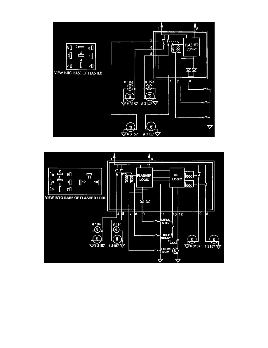
Electronic Combination Flasher Circuit
Electronic Combination Flasher With DRL Circuit
The battery input (Pin 1), is brought into the Junction Block through the Electrical Distribution Wiring (EDW) harness. It originates under the hood in
the Power Distribution Center (PDC) through a 20 ampere fuse at position 10 (9th position from the upper end) and labeled HAZARD. This circuit
(L09) is the only power feed to the combination-flasher/ DRL.