
Prowler V6-3.5L VIN G (1999)
Valve Spring I.D.
The valve springs are of two different lengths and are wound in different directions. The valve springs are color coded, intake spring is right hand coil
direction with orange dye on the top coils and the exhaust spring is left hand coil direction with a green dye on the top coils.
Valve Installation
1. Coat valve stems with clean engine oil and insert them in cylinder head.
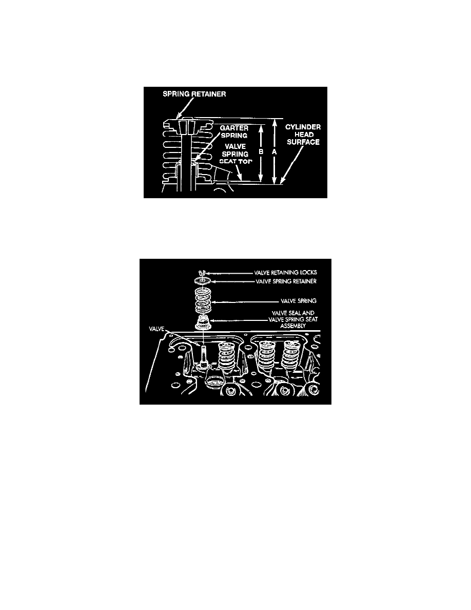
Checking Valve Tip Height And Valve Spring Installed Height
2. If valves or seats have been reground, check valve tip, height (A). If valve tip height is greater than 43.65 mm (1.7185 inch) intake or 45.98 mm
(1.8102 inch) exhaust, grind valve tip until within specifications. Make sure measurement is taken from cylinder head surface to the top of valve
stem.
Valve Seal And Spring Installation
3. Install valve seal/spring seat assembly over valve guides on all valve stems. Ensure that the garter spring is intact around the top of the rubber seal.
Install valve springs, valve retainers.
4. Compress valve springs with a valve spring compressor install locks and release tool. If valves and/or seats are reground, measure the installed
height of springs (B), make sure measurements are taken from top of spring seat to the bottom surface of spring retainer. If height is greater than
38.75 mm (1.5256 inch), install a 0.762 mm (0.030 inch) spacer in head counterbore under the valve spring seat to bring spring height back
within specification.