
Bonneville V6-231 3.8L VIN 3 SFI (1988)
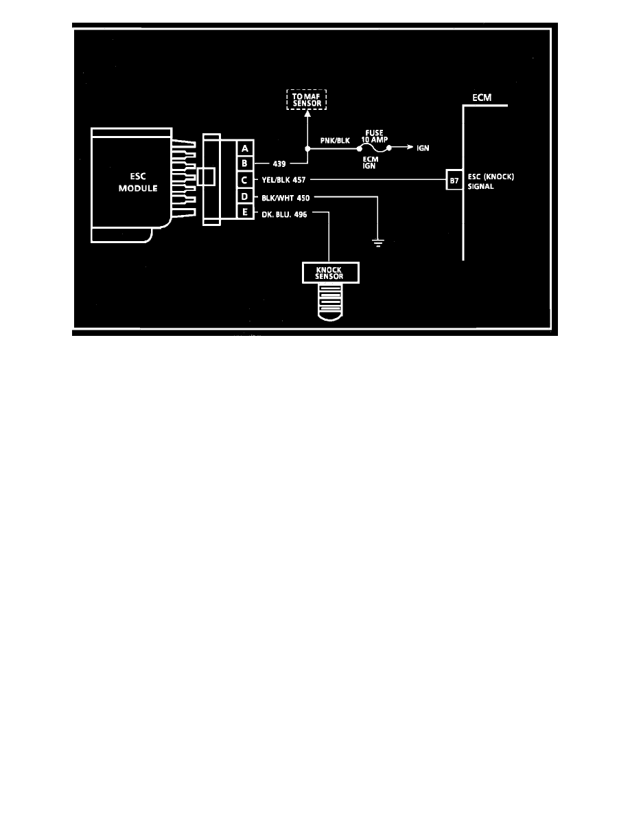
Wiring Diagram for Chart C-5 Electronic Spark Control System Check
CHART C-5 ELECTRONIC SPARK CONTROL (ESC) SYSTEM CHECK
Circuit Description:
The ESC system is comprised of a knock sensor and an ESC module. As long as the ESC module is sending a voltage signal (8 to 10 volts) to the ECM
(no detonation detected by the ESC sensor) the ECM provides normal spark advance. When the sensor detects detonation, the module turns "OFF" the
circuit to the ECM and the voltage at ECM terminal "B7" drops to 0 volts. The ECM then retards EST as much as 20 degrees to reduce detonation. This
happens fast and frequently enough that if looking at this signal with a DVM, you won't see 0 volts, but an average voltage somewhat less than what is
normal with no detonation. A loss of the knock sensor signal or a loss of ground at ESC module would cause the signal at the ECM to remain high. This
condition would result in the ECM controlling EST as if no detonation were occuring. The EST would not be retarded, and detonation could become
severe enough under heavy engine load conditions to result in preignition and potential engine damage. Loss of the ESC signal to the ECM would cause
the ECM to constantly retard EST. This could result in sluggish performance and cause a Code 43 to set.
Test Description: Numbers below refer to circled numbers on the diagnostic chart.
1.
Tests ESC system's ability to detect detonation and retard the ignition timing.
2.
By disconnecting the ESC module, the ECM monitors a low voltage at terminal "B7" and should retard the ignition timing.
3.
After approximately 4 seconds, the "Service Engine Soon" light will come "ON" and Code 43 will be stored.
4.
Checks for proper voltage output (measured on A/C scale) of knock sensor. Low or no voltage would indicate an open circuit to terminal "E" or
faulty sensor.
5.
Checks to see if constant retard is due to a faulty knock sensor or module, or if a false voltage signal is being transmitted on the wire from the knock
sensor by induction from an adjacent wire, such as a spark plug wire, ignition wire, etc. Reroute wires as necessary.