
Firebird V8-350 5.7L VIN P SFI (1996)
6D1 for more details on BCM current draw in various awake and asleep conditions. For most BCM functions, the BCM will operate properly with a
system voltage of 9-16 volts.
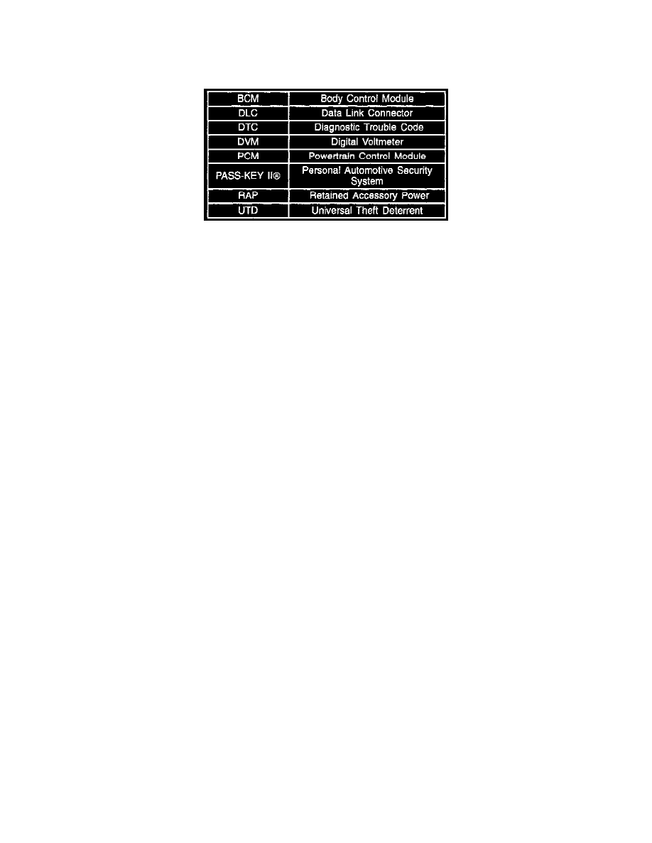
Abbreviations/Definitions
Several abbreviations are commonly used throughout this Section. They are presented here for easy reference.
On-Vehicle Service
Caution:
This vehicle is equipped with Supplemental Inflatable Restraint (SIR). Refer to CAUTIONS in Section 9J under "ON-VEHICLE SERVICE" and
the SIR component and Wiring Location view in Section 9J before performing service on or around SIR components or wiring. Failure to follow
CAUTIONS could result in possible air bag deployment, personal injury, or otherwise unneeded SIR system repairs.
BCM Replacement
Technicians should not replace the BCM unless specifically directed to do so by the diagnostics in this Manual. Most system concerns are
traceable to faulty wiring, connectors, or components. The BCM itself is very reliable, and is not likely the cause of a fault. BCM replacement
before complete diagnosis is performed will likely lead to a recurrence of the fault.
The BCM electrical connectors are designed with indexing tabs and slots, and will only fit one way. The connectors do not require excessive force
when installed correctly. Installing the connectors incorrectly can cause damage to the connectors, the BCM or other vehicle components or
systems. BCM removal/replacement procedures can be found below.
Component Locations/Removal Procedures
Below is a list of each component that a BCM diagnostic chart may direct you to replace. Use the list to determine which Section in the Manual
contains the removal and replacement procedures for the component in question. Refer below for BCM removal/replacement procedures.
BCM
8D
PCM
6E3
Instrument Cluster
8C
PASS Key II(R) Ignition Key
9D
Theft Deterrent Shock Sensor
9D
Theft Deterrent L.E.D.
9D
Entry Into Diagnostics
In the Diagnostic Mode, the BCM displays any Diagnostic Trouble Codes (DTCs) stored in memory. The DTCs are displayed as flash codes through the
"Security" indicator lamp on the Instrument Cluster. During normal operation, if the BCM detects a fault in a monitored system, there is no flash code to
indicate to the customer that a fault has occurred, though he/she may detect a system malfunction. System faults are stored by the BCM as "Current", or
"History" DTCs. A "Current" DTC means that the fault was present when the Diagnostic Mode was entered. A "History" DTC means the fault occurred
sometime after the BCM was installed in the vehicle (or since the last time the DTCs were cleared), but may not currently be present. If a "Current" DTC
is stored, the associated "History" DTC will always be stored. When working on systems controlled by the BCM, the technician should always refer to
this Section and check for DTCs.
Diagnostics is entered by performing the following steps:
^
Turn the Ignition Switch to the "RUN" position to disarm the Universal Theft Deterrent system, if equipped.
^
Turn the Ignition Switch to the "OFF" position.