
Grand Prix V6-3.8L VIN 2 (2004)
1. Set the rotary dial of the DMM to the V (DC) position.
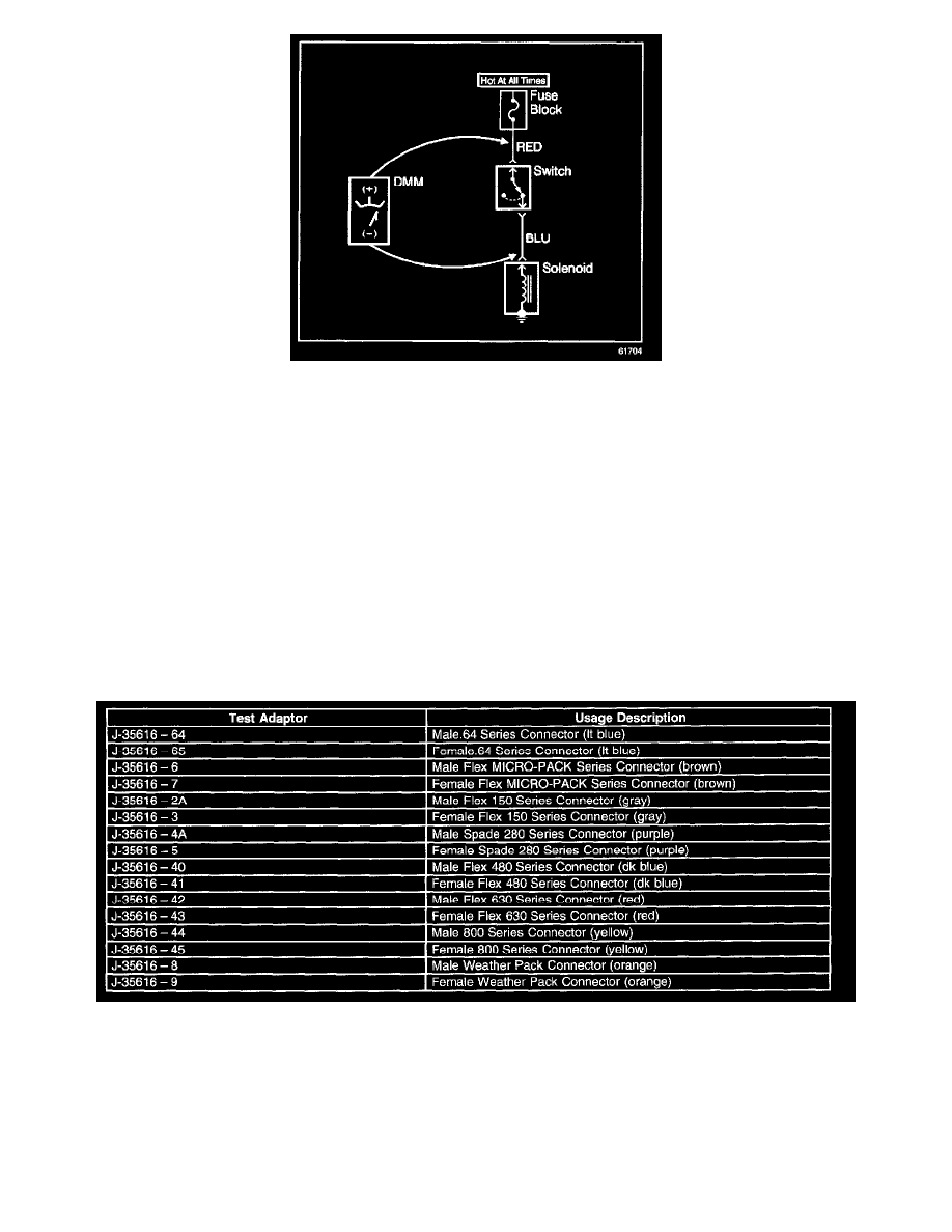
2. Connect the positive lead of the DMM to 1 point of the circuit to be tested.
3. Connect the negative lead of the DMM to the other point of the circuit.
4. Operate the circuit.
5. The DMM displays the difference in voltage between the 2 points.
Probing Electrical Connectors
PROBING ELECTRICAL CONNECTORS
IMPORTANT: Always be sure to reinstall the connector position assurance (CPA) and terminal position assurance (TPA) when reconnecting
connectors or replacing terminals.
Frontprobe
Disconnect the connector and probe the terminals from the mating side (front) of the connector.
NOTE: Do not insert test equipment probes into any connector or fuse block terminal. The diameter of the test probes will deform most terminals. A
deformed terminal can cause a poor connection, which can result in system failures. Always use the J 43907 Connector Test Adapter Kit in order to
frontprobe terminals. Do not use paper clips or other substitutes as they can damage terminals and cause incorrect measurements.
Refer to the shown table as a guide in selecting the correct test adapter for frontprobing connectors.
Backprobe
IMPORTANT:
-
Backprobe connector terminals only when specifically required in diagnostic procedures.
-
Do not backprobe a sealed (Weather Pack(R)) connector, less than a 280 series Metri-Pack connector, a Micro-Pack connector, or a flat wire
(dock and lock) connector.
-
Backprobing can be a source of damage to connector terminals. Use care in order to avoid deforming the terminal, either by forcing the test probe