
J2000/Sunbird V6-191 3.1L (1992)
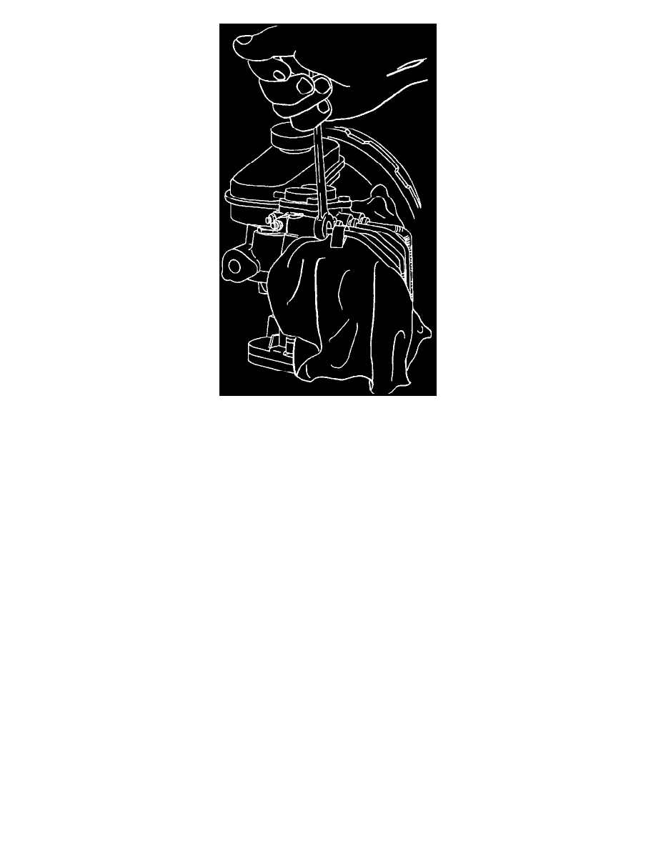
Brake Pipe Connections
^
Place shop cloth on top of motor pack to catch any dripping fluid. Take care not to allow brake fluid to enter the bottom of the motor pack or
the electrical connectors. Plug open lines to prevent fluid loss and contamination.
6. Two nuts attaching hydraulic modulator/master cylinder assembly to vacuum booster.
^
It may be necessary to remove vacuum check valve from vacuum booster to gain access to the nut closest to the check valve.
7. Hydraulic modulator/master cylinder assembly From vehicle.
INSTALL OR CONNECT
1. Hydraulic modulator/master cylinder assembly in vehicle.
^
It may be necessary to remove vacuum check valve From vacuum booster to gain access to the nut closest to the check valve.
2. Two nuts attaching hydraulic modulator/master cylinder assembly to vacuum booster.
TIGHTEN
^
Nuts to 27 Nm (20 lb. Ft.).
3. Four brake pipes to hydraulic modulator/master cylinder assembly.
TIGHTEN
^
Tube nuts to 17 Nm (13 lb. Ft.).
4. Motor pack 6-Pin and 3-Pin electrical connectors.
5. Fluid level sensor electrical connector.
6. Two solenoid electrical connectors.
^
Bleed system, refer to Brake Bleeding / Service and Repair.