
Sunfire L4-144 2.4L DOHC VIN T SFI (2001)
NOTE: Refer to Fastener Notice in Service Precautions.
20. Tighten the shaft nut against the crankshaft shoulder, using a 17.5 N.m (12.5 lb ft) torque wrench and the J 33022.
Tighten
Tighten the nut to 16.5 N.m (12 lb ft).
21. Spin the pulley rotor by hand in order to verify that the rotor does not rub the clutch drive plate.
V5 - Direct Mount
TOOLS REQUIRED
^
J 33013-B Hub and Drive Plate Installer
^
J 33027-A Clutch Hub Holding Tool
^
J 33017 Pulley and Bearing Assembly Installer
^
J 41790 Compressor Holding Fixture
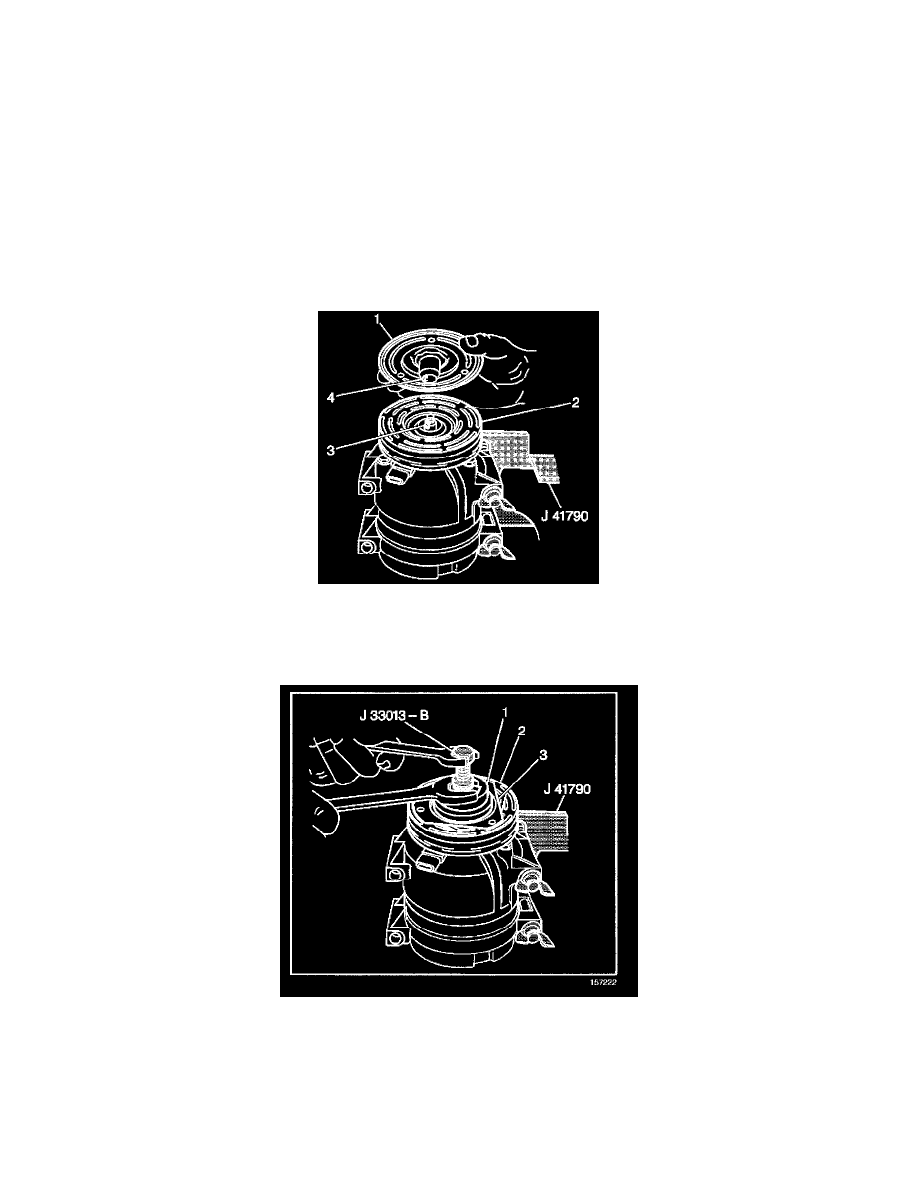
1. Install the shaft key into the hub key groove (4) approximately 3.2 mm (1/8 in) out of the keyway.
The shaft key is curved slightly to provide an interference fit in the hub key groove.
2. Clean the surfaces of the clutch plate (1) and the clutch rotor (2) before installing the clutch plate and hub assembly.
3. Align the shaft key with the shaft keyway in the clutch plate and the hub assembly and place onto the compressor shaft (3).
4. Remove the J 33013-B.
4.1.
Remove the center screw from the body of the hub and drive plate installer.
4.2.
Install the center screw into the opposite end of the hub and drive plate installer.
5. Install the J 33013-B and bearing tools (1) onto the clutch plate (3) and the hub assembly (2).
5.1.
Back the body of the hub and drive plate installer tool off enough to allow the center screw to be threaded onto the end of the compressor
shaft.
5.2.
Thread the center screw several turns onto the end of the compressor shaft.
Do not tighten the center screw on the compressor shaft.