
L300 V6-3.0L VIN R (2001)
BCM Power And Ground Circuit Chart
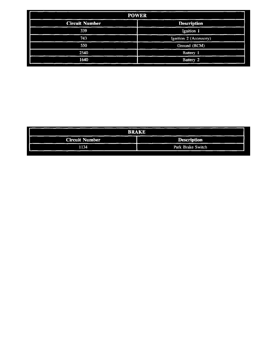
Circuit assignments for the Body Control Module (BCM) relating to device power:
BCM Replacement
If unable to communicate with the original BCM, the last value displayed by the cluster must be entered into the new BCM with the Saturn Service Stall
during reprogramming.
Brake Circuit Chart
Circuit Chart
Circuit assignments for the Body Control Module (BCM) relating to device brake:
BTSI Solenoid
The Brake Transaxle Shift Interlock (BTSI) solenoid is energized by the BCM switching circuit 816 to ground. When energized, the BTSI solenoid will
allow shifting from PARK. A condition for shifting from PARK is that the foot brake must be applied. The BCM receives this information over the serial
data link from the engine controller.
The BCM also monitors ignition 1 circuit 339 and ignition 2 circuit 743 to determine if the ignition switch is in the RUN or ACC position.
Can Communications (V - 6 Only)
The Engine Control Module (ECM) and the Transaxle Control Module (TCM) communicate with each other over the CAN (controller area network)
bus circuit 2501 and circuit 2500. The CAN bus is a communication link similar to class II.
The Body Control Module (BCM) acts as the interpreter or gateway between the other modules connected to the class II serial data circuit 1807 and the
ECM and TCM connected to the CAN bus circuit 2501 and circuit 2500.
State Of Health (SOH) messages are sent from the ECM and TCM to the BCM when the ignition is turned ON and during vehicle operation. These
messages tell the BCM the ECM and TCM are working correctly. The BCM has an internal reset counter to monitor the status of the CAN bus. When
the counter reaches a defined value and no CAN messages have been received from either the ECM or TCM, the BCM sets DTC U2104 - CAN Bus
Reset Counter Overrun.
Class II Communications
The class II serial data circuit 1807 is used to communicate information between modules (for example the body control module and the engine
controller).
Contained in each module's memory is a list of serial data messages that are important and should he received by the module. Also contained are the
default actions to be taken by the module, if one of the important messages is not received in time. One of those important messages is the State Of
Health (SOH) message. This message is sent by a module (if no other message needs to be sent) to let all the other modules on the serial data circuit
know the sending module is working correctly.
Each time the ignition is turned ON, all the modules on the class II serial data circuit first learn the other modules connected to the class II serial data
circuit. Modules are able to learn the other modules on the serial data circuit because each of the important messages has a source identifier as part of the
message.