
SW2 L4-1.9L DOHC VIN 7 (1997)
19. Remove the intake manifold support brace bolt attached to the intake manifold located next to the generator.
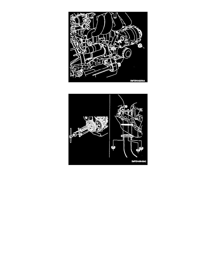
20. Remove front damper/pulley assembly. Hold damper with a strap wrench or use a 3/4 inch square x 12 inch long piece of wood wedged between
the damper spoke and rear, lower side of front cover when removing the bolt. Puller jaw slots are cast into damper/pulley assembly for removal
with a small three jaw puller if required.
21. Disconnect exhaust pipe from exhaust manifold. Remove the three nuts from the flange.
22. Removal of the front cover assembly:
a. Install the crankshaft gear retaining service tool SA9104E to make sure the front crankshaft timing sprocket is held firmly in place.
CAUTION: Install service tool SA9104E with flat side toward sprocket. Failure to hold the crankshaft timing sprocket in place will cause
timing chain guide damage. This tool also aligns the oil pump gerotor during front cover installation. After the front cover assembly is
loosened and moved approximately 25.4 mm (1 inch) from the engine, the crankshaft timing gear service tool should be removed. Spray the
two dowel pin holes in the front cover with penetrating oil to prevent cover damage during removal.
b. Remove the four front oil pan bolts.