
VUE AWD V6-3.5L VIN 4 (2004)
Multiple Junction Connector: All Technical Service Bulletins
Engine Controls - SES Lamp ON/Driveability Issues
Bulletin No.: 06-06-03-005
Date: June 19, 2006
TECHNICAL
Subject:
Service Engine Soon (SES)/Malfunction Indicator Lamp (MIL) On and/or Engine Driveability Concerns (Wiggle ECM/PCM Connector and Replace
Connector, If Necessary)
Models:
2004-2006 Saturn VUE with 3.5L V6 Engine (VIN 4 - RPO L66)
2005-2006 Saturn ION with 2.2L 4-Cylinder Engine (VIN F - RPO L61)
Condition
Some customers may comment on the SES/MIL light coming on and/or engine driveability concerns. If the customer concern cannot be duplicated or
eliminated, wiggling the ECM/PCM connector on the affected vehicles may cause the symptoms to manifest.
Cause
This condition may be caused by damage to the retention feature on the connector body. This allows the connector to lose clamp load to the control
module, which may cause intermittent connections between the control module and wiring harness.
Correction
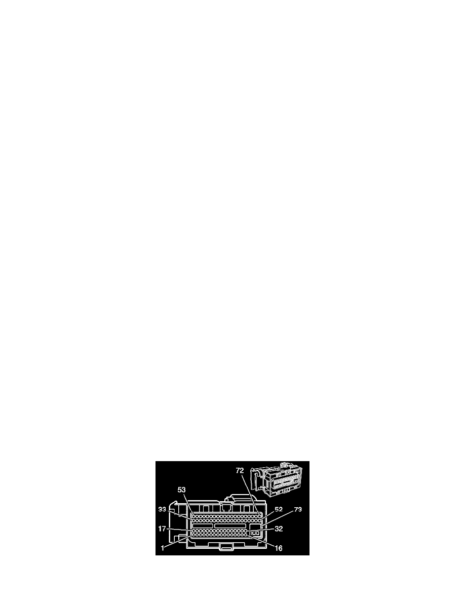
Do NOT replace the complete engine wiring harness if the condition can be duplicated by wiggling the 73-way ECM/PCM connector.
If this condition can be duplicated by wiggling the 73-way ECM/PCM connector, replace the connector following the procedure below:
Connector Replacement
1.
Disconnect the negative battery cable. Refer to Battery Negative Cable Disconnection and Connection in SI.
2.
For the Saturn VUE only, remove the upper air cleaner housing lid and the air cleaner resonator outlet duct. Refer to Air Cleaner Resonator Outlet
Duct Replacement in SI.
3.
Disconnect both the body and the engine harness connector at the ECM/PCM.
Note:
Do not rotate or turn the J 35616-64A or J 35616-64B when it is inserted into a terminal. The square cross-section of the tool may loosen the
terminal if the tool is rotated.
4.
Perform a terminal tightness check on all terminals using the J 35616-64A or J 35616-64B. If there are any loose terminals, replace the terminals
and retest prior to performing Step 5. Refer to Delphi Connectors (Micro .64 Connectors) in SI.
5.
Rotate the engine harness connector cam lock forward to the released position. Remove the connector top cover and then cut and remove the cable
tie strap that retains the wire to the body of the connector.
6.
On the connector face, remove the blue protective sleeve for the ground wire (at pin 73). Remove the ground wire (pin 73) by moving the tab away
from the terminal on the connector face and pulling on the wire from the backside.