seat Workshop Repair Guides

SEAT Workshop Service and Repair Manuals

Engine lubrication > < Removing and installing cylinder head
Valve stem seals: replace when cylinder head is installed
   
Valve stem seals: replace when cylinder head is installed
Consult the equivalence table for tools and equipment according to applicability among Seat / VW / Audi / Skoda → Chapter.
Special tools and workshop equipment required
t  Extension and socket -3220-, see equivalent → Anchor
t  Extractor -3364-, see equivalent → Anchor
t  Pressure tool -3365-, see equivalent → Anchor
t  Valve installation kit -VAS 5161- with guide plate -VAS 5161/23- and knurled spacer ring -VAS 5161/23-1-, see equivalent → Anchor

Operation process
–  Use jointed spanner -3220- to remove all glow plugs → Chapter.
–  Remove camshafts → Chapter.
   
–  Fit guide plate -VAS 5161/23- onto cylinder head.
–  Secure the guide plate on the intake manifold side with the knurled screw -VAS 5161/12- and on the stud with collarless M6 nuts -1-, which are tightened manually.
–  Screw the Sealing bolts -VAS 5161/10- in the guide plate.
  N15-10450
–  Screw adapter -VAS 5161/11- into corresponding glow plug thread such that it is hand-tight.
  N15-10451
–  Attach the Mandrel -VAS 5161/3- in the guide plate and remove the fixed wedges from the valves with a rubber hammer.
  N15-10452
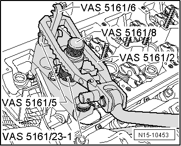
–  Screw engaging fork -VAS 5161/5- with snap-in device -VAS 5161/6- into guide plate.
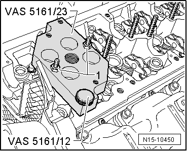
–  Slide the knurled spacer ring -VAS 5161/23-1- on the assembly cartridge -VAS 5161/8-.
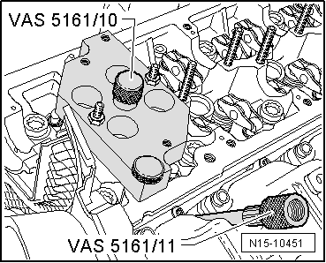
–  Connect adapter -VAS 5161/11- by way of a commercially available adapter piece to compressed air supply and constantly apply pressure.
l  Minimum pressure: 6 bar
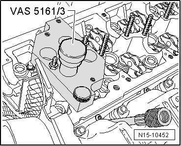
–  Connect the pressure fork -VAS 5161/2- of the tool and press the assembly cartridge downwards.
–  At the same time, turn the knurled screw of assembly cartridge to the right until the tips engage in valve collets.
–  To disengage the cotter from the valves, move the knurled screw a little and mount the cotter in the assembly cartridge.
–  Release pressure fork.
–  Remove the assembly cartridge with a knurled spacer ring, valve head and valve spring.
  N15-10453
–  Remove valve stem oil seals using the valve stem seal puller -3364-.
  Note
  N15-10454
A plastic sleeve -A- is included with the new valve stem oil seals.
–  Fit the plastic sleeve -A- onto the valve stem to prevent damage to the new valve stem seals -B-.
–  Grease the sealing lip of the valve stem seal lightly.
–  Slide valve stem oil seal onto plastic sleeve.
–  Carefully fit the valve stem seal on the valve guide with the valve stem seal fitting tool -3365-.
–  If required, strike lightly with a plastic hammer till the valve stem seal is pressed as far as possible.
–  Remove plastic sleeve again.
–  Reset the valve spring and the valve head on the cylinder head.
  A15-0282
–  If the valve cotters were removed from the assembly cartridge, they must be first set in the fixture -VAS 5161/18-.
  Note
Larger diameter of valve cotters faces upwards.
–  Press the assembly cartridge onto the insertion device from above and pick up valve cotters.
  A15-0445
–  Insert the assembly cartridge -VAS 5161/8- back in the guide plate.
–  Lower the pressure fork and pull towards the knurled screw and at the same time turn towards the left and right. With this the valve cotters are set.
–  Reduce pressure on pressure fork whilst pulling on knurled screw.
Installation is carried out in the reverse order; note the following:
–  Install glow plugs → Chapter.
–  Install camshafts → Chapter.
  Note
t  After installing cam shaft, the engine must not be started for approx. 30 minutes. Hydraulic compensation elements must be set. (Else the valves fit on the pistons).
t  After working on the valve gear, turn the engine carefully at least 2 rotations to ensure that none of the valves make contact when the starter is operated.
  N15-10453

Engine lubrication > < Removing and installing cylinder head