seat Workshop Repair Guides

SEAT Workshop Service and Repair Manuals

Installing > < Removing and installing mounting bracket
Removing
Removing
LHD
–  First the vehicle should be checked if a coded radio is installed. If necessary obtain radio anti-theft code first.
–  Remove the entire air filter housing if it is located in the battery area → Rep. gr.23.
–  Remove battery and battery tray → Electrical system; Rep. gr.27.
Right-hand drive vehicles
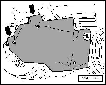
An insulation mat is installed before the master cylinder in conjunction with some engines. Appearance may be different from that illustrated.
   
–  Remove heat shield mat -arrows-, if present.
Continuation for all vehicles
  Note
t  During the following work, ensure that no brake fluid lands on longitudinal member or gearbox. If this does happen, clean the affected areas thoroughly.
  N34-11205
t  Fit a lint-free cloth under the clutch master cylinder.
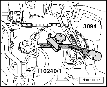
–  Seal the supply hose leading to the clutch master cylinder using the sealing tool -T10249/1-.
  Note
The hose clamps -3094- that appear in the figure can be ignored.
  N30-10217
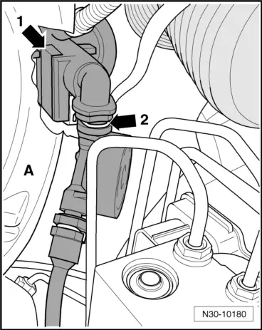
Clutch position sender -G476--arrow 1- and securing clip -arrow 2- must be removed during the further procedure. These are located near brake servo -A- and are partly covered by it.
  N30-10180
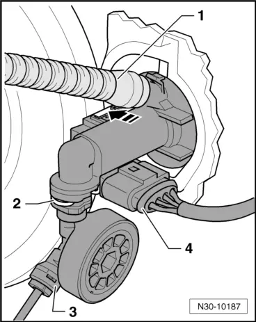
–  Pull supply hose -1- off master cylinder.
–  Release securing clip -2- and pull line -3- off master cylinder.
–  Unclip clutch position sender -G476- near supply hose -1- from master cylinder -arrow- and remove with connector attached -4-.
  Note
When performing work in the footwell, put cloths on the carpet to protect it from possible brake fluid spills.
–  Remove driver side compartment and cover → General body repairs, interior; Rep. gr.68.
Vehicles with knee airbag
–  Remove knee airbag → Interior equipment; Rep. gr.69.
  N30-10187
Continuation for all vehicles
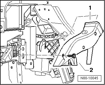
–  Remove footwell vent -1- → Heater; Rep. gr.80.
  N80-10045
Appearance of footwell vent may differ from illustration.
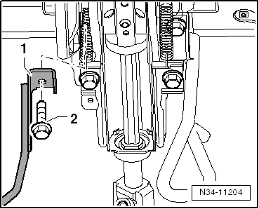
–  Remove impact absorber -1-. To do this, remove the bolt -2-.
–  Unbolt fuse holder beneath dash panel on left and lay to side → Electrical system; Rep. gr.97.
–  Unhook relay carrier beneath dash panel on left and lay to side → Electrical system; Rep. gr.97.
  N34-11204
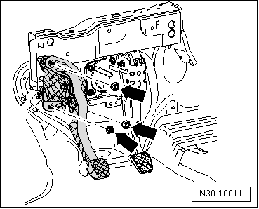
Remove mounting bracket securing nuts -arrows- as follows:
  N30-10011
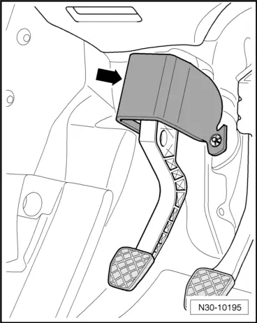
If fitted, remove damping -arrow- from lower area of clutch pedal mounting bracket.
  N30-10195
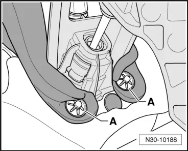
–  To do this, remove lock washers -A- for damping.
–  Pull off damping.
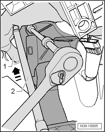
–  Mask universal joint of socket range 3/8" -VAG 1835- with insulating tape.
  N30-10188
–  Push wiring harness -1- upwards and to the left -arrow- using extension -2- of socket range 3/8" -VAG 1835-.
  N30-10005
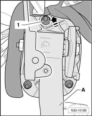
–  If damping is fitted, push it upwards in area of upper securing nut -1- above clutch pedal -A- in -direction of arrow-.
–  Unbolt upper securing nut -1- for mounting bracket.
The securing nut -1- is accessible between the relay carrier and the steering column.
  N30-10189
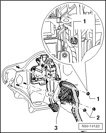
–  Then unbolt both lower securing nuts -2- for mounting bracket and remove mounting bracket.
–  Detach mounting bracket -3-.
–  Pull off the damping at the same time if it is fitted.
  N30-10123

Installing > < Removing and installing mounting bracket