seat Workshop Repair Guides

SEAT Workshop Service and Repair Manuals

Control unit and hydraulic unit: fitting > < Connection of the master brake cylinder brake pipes to the hydraulic unit
Control unit and hydraulic unit: removing
Consult the equivalence table for tools and equipment according to applicability between Seat / VW / Audi / Skoda → Chapter.
Special tools and workshop equipment required
   
t  Torque wrench kit -SAT 8010-
  L00-10226
t  Brake pedal block -VAG 1869/2-
Plugs from the repair kit → Parts catalogue
After removing the control unit of the hydraulic unit, the transportation protection for the hydraulic unit valve stems must always be applied.
  W00-0679
In the hydraulic units without transportation protection, no complaints are approved under guarantee.
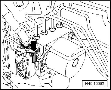
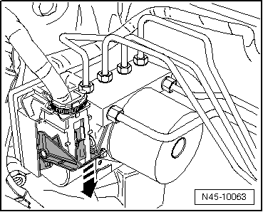
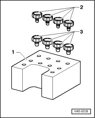
1 - Transport protection for the valve stems (cellular plastic)
2 - M 10 seal bolt
3 - M 12 seal bolt
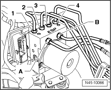
Installation location: The ABS control unit -J104- comes screwed to the ABS hydraulic unit -N55- and is located on the right side of the engine compartment, for vehicles with the steering wheel on the left side.
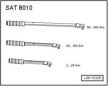
  WARNING
The brake lines should not be folded or kinked in area of the hydraulic unit
Removal:
  Note
t  Before disconnecting the battery, consult the customer regarding the anti-theft code provided with the radio.
t  If the battery is reconnected, check the vehicle equipment (radio, clock, comfort system, electric window lifter, etc.), following the indications in the Workshop Manual and/or the Operating Instructions.
  WARNING
Before working on the electrical system, disconnect the battery earth strap.
–  Disconnect battery.
–  Remove engine cover → Booklet1.
Vehicles with 1.9 litre/74 KW TDI engine
–  Remove the rear supercharger pipe: → Rep. Gr.21 .
–  Remove the upper connection pipe from the turbocharger hose intake sleeve → Rep. Gr.21 .
Continued for all vehicles
  N45-0039
–  Press down on the red safety rail -arrow-.
  N45-10062
–  Unlock the control unit connector -arrow- and remove it forward.
–  Fit the block for the brake pedal -VAG 1869/2-.
–  Operate the brake pedal using the block for the brake pedal -VAG 1869/2-.
–  Fit the bleeding tube from the bleeding bottle to the bleeding screw of the front left brake calliper and open it.
–  Close the front bleeding screw.
–  Do not remove the block from brake pedal.
–  Place a sufficiently large lint-free cloth under the control unit and the hydraulic unit.
  N45-10063
Make sure that brake fluid does not fall onto the connectors.
–  Mark the brake pipes running from the hydraulic unit -A- and -B- to the master cylinder. Unscrew them and attach in order to suspend them.
–  Immediately cover the brake lines and the threaded openings with the plugs from the repair kit → parts catalogue.
–  Mark the remaining brake pipes (to the brake calliper) -1 to 4-. Unscrew them from the hydraulic unit and plug.
  N45-10066
–  Remove the hexagonal nut -1- from the control unit securing point / hydraulic unit.
–  Remove the hydraulic unit along with the control unit and the support.
–  Unscrew the bracket from the control unit / hydraulic unit.
  N45-10071

Control unit and hydraulic unit: fitting > < Connection of the master brake cylinder brake pipes to the hydraulic unit