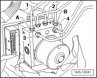
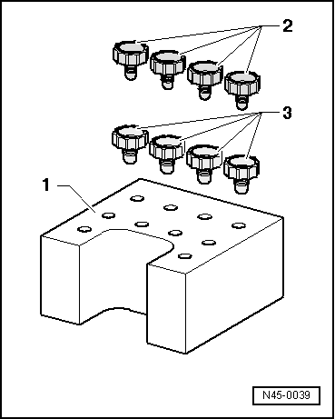
seat Workshop Repair Guides

SEAT Workshop Service and Repair Manuals

Unscrew the ABS control unitJ104 from the ABS hydraulic unit N55 > < Connection of the tandem master cylinder brake lines to the hydraulic unit
ABS control unit J104 and ABS control unit and ABS hydraulic unitN55 : removal.
ABS control unit -J104- and ABS control unit and ABS hydraulic unit -N55 -: removal.
Consult the equivalence table for tools and equipment according to applicability between Seat / VW / Audi / Skoda → Chapter.
Special tools and workshop equipment required
   
t  Brake pedal block -V.A.G 1869/2-, see equivalent → Anchor
  W00-0679
t  Calliper set for repairs; part number according to → Parts catalogue
1  - Valve dome transport protection (rubber foam).
2  - Caps M10 for brake lines and screw holes.
3  - Caps M12 for brake lines and screw holes.
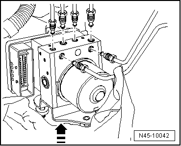
After removing the control unit of the hydraulic unit, the transportation protection for the hydraulic unit valve stems must always be applied.
No guarantee is given for hydraulic units without transport protection.
Removing
Location:
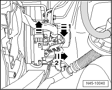
The control unit is bolted to the hydraulic unit and is located on the right side of the engine compartment.
  WARNING
The brake lines should not be folded or kinked in area of the hydraulic unit
–  Check and note the code for the control unit fitted.
–  Note or request radio code on vehicles with coded radio if necessary.
–  Disconnecting the battery → Electrical system; Rep. gr.27
–  Remove engine cover
1.9 l diesel engine:
–  Loosen the connecting hose on the intake support → 4 cylinder Diesel (2 valve); Rep. gr.21 .
–  Remove the intake manifold flap motor -V157- → 4-cylinder diesel (2 valves); Rep. gr.23 .
2.0l diesel engine:
–  Remove the front panel of the plenum chamber → Bodywork, exterior fitting work; Rep. gr.50 .
–  Remove the connection tube between the intake hose and the exhaust gas turbocharger.
–  Remove upper notched belt guard.
Diesel engines with particle filter:
–  Unbolt the exhaust gas pressure sensor 1, -G450 -disconnect electrical connections and unbolt and lower particulate filter → Front section of exhaust pipe with particulate filter: Assembly overview; Rep. gr.26 :
All vehicles (continued):
  N45-0039
–  Disengage the control unit connector in the direction shown on the arrow -1- and remove -2-.
–  Fit the block for the brake pedal -VAG 1869/2-.
–  Plug the hose of the air bleeding bottle to the vent valve of the brake calliper in the front and back left and open the vent valve.
–  Operate the brake pedal using the brake pedal block -VAG 1869/2- 60 mm minimum.
–  Close the front and rear left bleeding screws.
–  Do not remove the block for the brake pedal -VAG 1869/2-.
–  Place a sufficiently large lint-free cloth under the control unit and the hydraulic unit.
  WARNING
Make sure that brake fluid does not fall onto the connectors.
  N45-10040
–  Mark both brake master cylinder brake lines -A and B- before unscrewing them from the hydraulic unit.
–  Immediately cover the brake lines and the threaded openings with the plugs from the repair kit → Spare parts catalogue.
–  Mark the brake lines (brake calliper) -1 to 4 -, unscrew and plug.
  N45-10041
–  Pull the hydraulic unit with the control unit upwards to remove the shock absorbers.
  N45-10042

Unscrew the ABS control unitJ104 from the ABS hydraulic unit N55 > < Connection of the tandem master cylinder brake lines to the hydraulic unit