seat Workshop Repair Guides

SEAT Workshop Service and Repair Manuals

Removing and installing parts of ABS system on front and rear axles > < ABS/ESP Bosch 8.0
Hydraulic control unit: Removing and installing
Consult the equivalence table for tools and equipment according to applicability between Seat / VW / Audi / Skoda → Chapter.
Special tools and workshop equipment required
   
t  Torque wrench -V.A.G 1331-, see equivalent → Anchor.
  W00-0427
t  Brake pedal depressor -V.A.G 1869/2-
t  Plugs from the repair kit → Parts catalogue
After removing the control unit of the hydraulic unit, the transportation protection for the hydraulic unit valve stems must always be applied.
  W00-0679
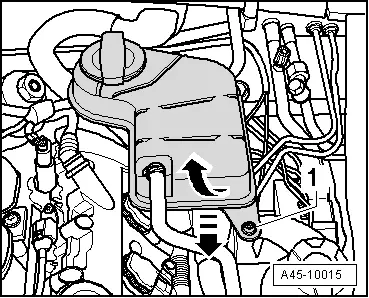
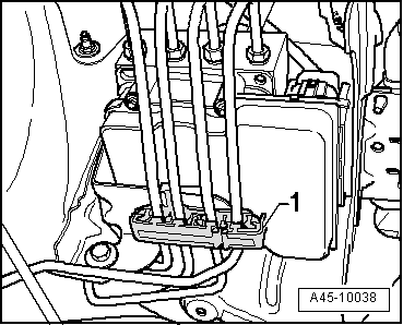
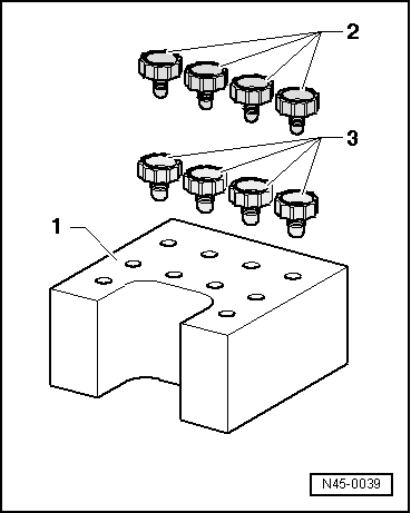
No guarantee is given for hydraulic units without transport protection.
1 - Transport protection for the valve stems (cellular plastic)
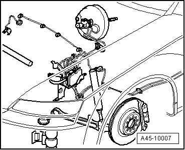
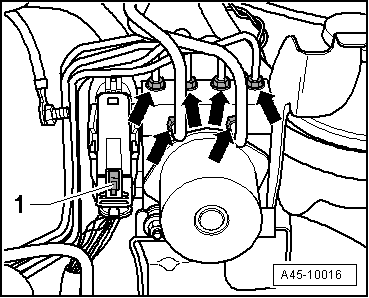
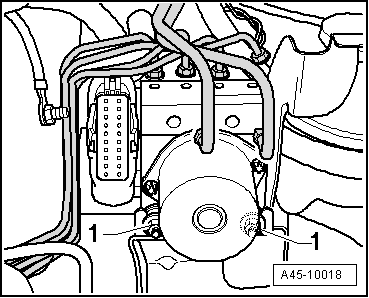
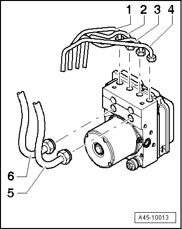
2 - M 10 seal bolt
3 - M 12 seal bolt
  WARNING
The brake lines should not be folded or kinked in area of the hydraulic unit
Removal:
  Note
t  Before disconnecting the battery, consult the customer regarding the anti-theft code provided with the radio.
t  If the battery is reconnected check the vehicle equipment (radio, clock, electric comfort system, etc.), following the indications in the Workshop Manual and/or the Operating Instructions.
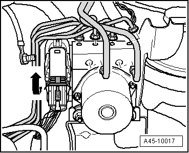
  WARNING
Before working on the electrical system, disconnect the battery earth strap.
Installation location:
  N45-0039
The hydraulic control unit is fitted on the left-hand side of the engine compartment.
–  Disconnect battery . → Rep. gr.27
  A45-10007
–  Unscrew bolt -1- from coolant expansion reservoir.
  A45-10015
–  Disconnect connector -1- from expansion reservoir.
–  Lay down expansion reservoir at side.
  A45-10014
–  Fit the brake pedal lock -V.A.G 1869/2- between the brake pedal and the driver's seat. Push the brake pedal by at least 60 mm.
–  Connect the hose of the bleeder bottle to the calliper air bleeder bolts, front and rear on the left hand side, open the bleeder bolts.
  Note
This reduces the pressure in the hydraulic unit.
–  Close bleeder screws at front left and rear left.
–  Do not remove the block for the brake pedal -V.A.G 1869/2-.
  Note
t  Protect area located below control unit and hydraulic unit with lint-free cloth in case of brake liquid escape.
t  Number brake lines.
  WARNING
Do not bend the brake lines in the area of the hydraulic unit.
  A44-0020
–  Disconnect brake lines between hydraulic unit and brake master cylinder completely.
–  Disconnect remaining brake lines -arrows- on hydraulic unit.
–  Seal brake lines and tapped holes with sealing plugs from repair kit.
  A45-10016
–  Open brake line bracket -1-.
  A45-10038
–  Push red safety slider -1- upward.
  Note
t  Make sure brake fluid does not get into connector housing of control unit. This would cause corrosion of the pins and result in a total system failure.
t  Use compressed air to carefully clean connector housing if necessary.
  A45-10016
–  Push retaining clip in -direction of arrow- and unplug connector.
  A45-10017
–  Remove hexagon bolts -1-.
–  Remove the hydraulic unit.
Installation
  WARNING
To ensure that the brake system and all electronic brake control systems function correctly and safely, it is important to bleed the entire brake system and its hydraulic components correctly. The ABS hydraulic uni -N55- must be filled before performing the customer service.
Installation is carried out in the reverse sequence; note the following:
  Note
t  Only remove the plugs from the new hydraulic unit once the corresponding brake pipe is fitted.
t  If the plugs are removed from the hydraulic unit beforehand, brake fluid could flow out, for which the filling and bleeding of the system could not be guaranteed.
  Note
t  Do not apply excess force to the centre of the unit when assembling.
t  Static electricity should be discharged to prevent damage to the unit or to the built-in senders.
t  If the nuts for fastening the hydraulic unit mount are removed from the body, do not tighten them completely. This will make it easier to attach the individual brake lines to the hydraulic unit.
  A45-10018
–  Connect lines according to marking:
1  - To front right brake calliper
2  - To rear left brake caliper
3  - To rear right brake caliper
4  - To the front left brake calliper
5  - To primary piston circuit
6  - To secondary piston circuit
–  Fit connector on hydraulic pump.
–  After connecting brake lines, firmly tighten hydraulic unit.
–  Remove the block for the brake pedal -V.A.G 1869/2-.
–  Tighten brake lines with specified tightening torque → Anchor.
–  Bleeding air from the brake system → Chapter.
–  Code the radio.
–  Code the ABS control unit -J104 -.
–  Connect the vehicle diagnostic, testing and information system -VAS 505X- and select the function → Chapter
  Note
Final control diagnosis can be used to establish whether line connections have been interchanged → Chapter.
Tightening torques
  A45-10013
Component Nm
Brake lines to hydraulic unit M10 (ø 5 mm brake line)12
Brake lines to hydraulic unit M12 (ø 5 mm brake line)12
Brake lines to hydraulic unit M12 (ø 8 mm brake line)16


Removing and installing parts of ABS system on front and rear axles > < ABS/ESP Bosch 8.0