
Leon Mk2
 Note
Note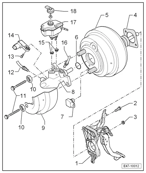
| 1 - | Pedal cluster |
| 2 - | Bolt, 25 Nm |
| 3 - | Self-locking nut: 25 Nm |
| q | Replace after each removal |
| 4 - | Seal |
| q | For brake servo. |
| 5 - | Brake servo |
| q | In petrol engines the vacuum required is taken from the intake manifold. |
| q | Some vehicles with petrol engines and automatic gearboxes are fitted with a brake vacuum pump -V192- → Chapter |
| q | Vehicles with reinforced hydraulic servo brake (HBV) are fitted with a servo brake vacuum sender -G483- → Item |
| q | In diesel engines the vacuum is obtained by a fitted vacuum pump → Chapter |
| q | Functional check: |
| – | With engine off, press the brake pedal hard several times (this reduces the existing vacuum in the servo brake). |
| – | Next, keep the brake pedal depressed halfway and start engine. If the brake servo is functioning properly, the brake pedal will be felt to go down as the servo takes effect. |
| q | If faulty, renew as a complete unit. |
| q | Separating from the brake pedal → Chapter |
| q | Removing and installing → Chapter |
| 6 - | Sealing ring |
| 7 - | Servo brake vacuum sender -G483- |
| q | Only in vehicles fitted with HBV (reinforced hydraulic servo brake) |
| q | Removing and installing → Chapter |
| 8 - | Brake master cylinder |
| q | After week 45/ 05 with brake light switch -F- |
| q | In vehicles manufactured prior to week 45/05, the brake light switch -F- is located on the brake pedal → Chapter |
| q | Allocation: → Parts catalogue |
| q | Cannot be repaired. If faulty, renew as a complete unit. |
| q | Removing and installing → Chapter |
| 9 - | Heat shield |
| 10 - | Nut, 50 Nm |
| 11 - | Bolt, 25 Nm |
| 12 - | Brake line, 14 Nm |
| q | From secondary piston circuit of brake master cylinder to hydraulic unit. |
| 13 - | Torx screw 5 Nm |
| 14 - | Brake pedal position sender -G100- |
| q | In vehicles manufactured prior to week 45/05, the brake light switch - F- is located on the brake pedal → Chapter |
| q | Removing and installing → Chapter |
| 15 - | Seal cap |
| q | Moisten with brake fluid and place the brake fluid reservoir under pressure |
| 16 - | Brake line, 14 Nm |
| q | From primary piston circuit of brake master cylinder to hydraulic unit. |
| 17 - | Brake fluid reservoir |
| 18 - | Plug |