
Leon Mk2
| Electrical/electronic components and fitting locations |
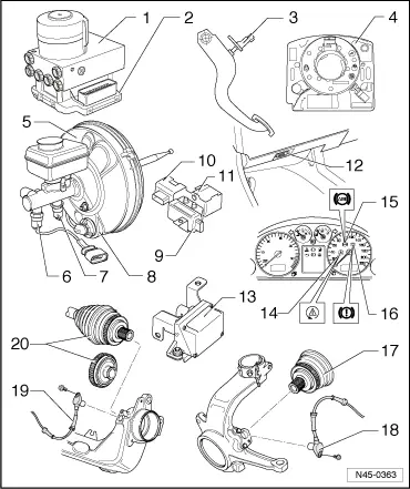
| 1 - | ABS hydraulic unit -N55- |
| q | Location: on left in engine compartment. |
| q | In the hydraulic unit, the ABS hydraulic pump -V64- and the intake/exhaust valves are checked via self-diagnosis |
| q | ABS hydraulic pump -V64- and valve block must not be separated from one another. |
| q | Removing and installing → Chapter. |
| 2 - | Control unit for ABS with EDL -J104- |
| q | Location: on hydraulic unit on left of engine compartment, testing is carried out via self-diagnosis |
| q | Do not disconnect multi-pin connector before self-diagnosis has been completed. Switch ignition off before separating connector. |
| q | Removing and installing → Chapter. |
| 3 - | Brake light switch -F- |
| q | The brake light switch is open in the rest position |
| q | Adjusting brake light switch → Chapter. |
| q | Allocation → Electronic Parts Catalogue (ETKA). |
| 4 - | Steering angle sender -G85- |
| q | Location: On steering column between steering wheel and steering column switches. |
| q | Removing and installing → Chapter. |
| 5 - | Brake servo |
| The brake servo consists of the following components: |
| q | Brake pressure solenoid trip switch -F84- |
| q | Brake pressure solenoid -N247- |
| q | Removing and installing → Chapter. |
| 6 - | Brake pressure sender 1 -G201- |
| q | Only vehicles with ABS/EDL/TCS/ESP. |
| q | Location for brake pressure sender 1 -G201- may also be position 7, brake pressure sender 2 -G214-. |
| q | Removing and installing → Chapter. |
| 7 - | Brake pressure sender 2 -G214- |
| q | Only vehicles with ABS/EDL/TCS/ESP. |
| q | Brake pressure sender 2 -G214- is not available in Mark 25. |
| q | Location for brake pressure sender 2 -G214- may also be position 6, brake pressure sender 1 -G201-. |
| q | Removing and installing → Chapter. |
| 8 - | Opening for cables |
| q | Brake pressure solenoid trip switch -F84- |
| q | Brake pressure solenoid -N247- |
| 9 - | Yaw rate sender -G202- |
| q | For vehicles with ABS/EDL/TCS/ESP Mark 20 only. |
| q | Location: Under driver's seat. |
| q | Removing and installing → Chapter. |
| 10 - | Lateral acceleration sender -G200- |
| q | For vehicles with ABS/EDL/TCS/ESP Mark 20 only. |
| q | Location: Under driver's seat. |
| q | Removing and installing → Chapter. |
| 11 - | Longitudinal acceleration sender -G251- |
| q | For four-wheel drive vehicles with Haldex clutch only |
| q | Location: Under driver's seat. |
| q | Removing and installing → Chapter. |
| 12 - | Diagnostic connection |
| q | Location: On the left under the central electrical unit. |
| 13 - | ESP sensor unit -G419- |
| q | For vehicles with ABS/EDL/TCS/ESP Mark 25 only. |
| q | Location: Under driver's seat. |
| q | Combined lateral acceleration sender -G200-, yaw rate sender -G202- and longitudinal acceleration sender -G251- → Note. |
| q | Combined in one housing. |
| q | Removing and installing → Chapter. |
| 1) | For four-wheel drive vehicles with Haldex clutch only |
| 14 - | Stabilisation program warning lamp -K155- |
| q | Location: in dash panel insert. |
| 15 - | ABS warning lamp -K47- |
| q | Location: in dash panel insert. |
| 16 - | Brake system warning lamp -K118- |
| q | Location: in dash panel insert. |
| 17 - | Wheel hub with rotor for speed sensors |
| q | Front right and left rotor and speed sensor are common parts |
| q | Removing and installing → Running gear, axles, steering; Front and four-wheel drive; Rep. Gr.40 |
| 18 - | Front right speed sensor -G45- / front left speed sensor -G47- |
| q | Removing and installing → Chapter. |
| 19 - | Rear right speed sensor -G44- / rear left speed sensor -G46- |
| q | Removing and installing → Chapter. |
| 20 - | Wheel hub with rotor for speed sensors |
| q | Rotor and speed sender for rear left and right-hand sides are common parts. |
| q | Removing and installing → Running gear, axles, steering; Front and four-wheel drive; Rep. Gr.42 |